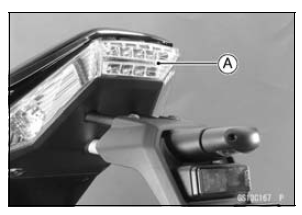


If it does not, adjust the brake light switch.
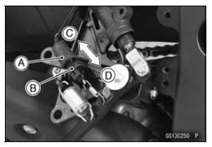
Switch Body [A] Adjusting Nut [B] Light sooner as the body rises [C] Light later as the body lowers [D]

NOTICE
To avoid damaging the electrical connections inside the switch, be sure that the switch body does not turn during adjustment.
If it does not go on, inspect or replace the following parts.
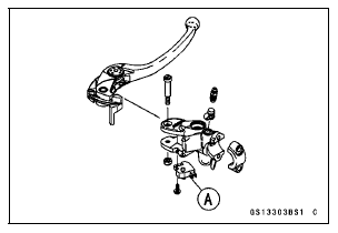
Battery (see Charging Condition Inspection in the Electrical System chapter) Brake Light (LED) (see Tail/Brake Light (LED) Removal Installation in the Electrical System chapter) Main Fuse 30 A and Brake Light/Horn Fuse 10 A (see Fuse Inspection in the Electrical System chapter) Front Brake Light Switch [A] (see Switch Inspection in the Electrical System chapter) Rear Brake Light Switch (see Switch Inspection in the Electrical System chapter) Harness (see Wiring Inspection in the Electrical System chapter)

 Brake Operation Inspection
 Suspension
Fuel Tank Installation
Note the above WARNING (see Fuel Tank Removal).
Run the hoses correctly (see Cable, Wire, and Hose Routing
section in the Appendix chapter).
Check that the dampers [A] are in place on the fuel tank.
If the dampers are damaged or deteriorated, replace
them.
If the fuel tank brack ...
KIBS Warning Indicator Light (For models equipped
with KIBS)
The yellow warning indicator light in
the meter unit functions as the KIBS
warning indicator light. The yellow
warning indicator light and warning
symbol “KIBS” go on if there is a malfunction
in the KIBS system. When the
warning light is on, the KIBS system
stops functioning. However, th ...
Oil Pump Installation
Install the outer rotor [A] into the crankcase.
Assemble:
Oil (Water) Pump Shaft [B]
Pin [C]
Inner Rotor [D]
To prevent dropping, apply grease to the pin.
Install the inner rotor assembly into the crankcase.
Fit the slot [E] onto the projection [F].
Replace the O-ring [A ...