
NOTE
Do not move the connecting rod and crankshaft during clearance measurement.
Remove the connecting rod big end again, measure each clearance between the bearing insert and crankpin [A] using plastigage (press gauge) [B].
NOTICE
After measurement, replace the connecting rod bolts and nuts.
Connecting Rod Big End Bearing Insert/Crankpin Clearance
Standard: 0.030  0.060 mm
(0.0012  0.0024 in.)
Service Limit: 0.10 mm (0.0039 in.)
If the clearance is within the standard, no bearing replacement is required.
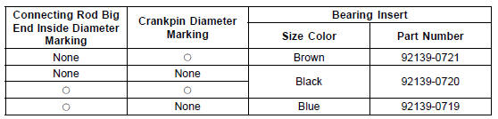
If the clearance is between 0.061 mm (0.0024 in.) and the service limit (0.10 mm, 0.0039 in.), replace the bearing inserts [A] with inserts painted blue [B]. Check insert/ crankpin clearance with the plastigage. The clearance may exceed the standard slightly, but it must not be less than the minimum in order to avoid bearing seizure.
If the clearance exceeds the service limit, measure the diameter of the crankpins.
Crankpin Diameter
Standard: 34.484  34.500 mm
(1.3576  1.3583 in.)
Service Limit: 34.47 mm (1.3571 in.)
Crankpin Diameter Marks
None 34.484  34.492 mm (1.3576
1.3580 in.)
 34.493
 34.500 mm (1.3580
 1.3583 in.)
 : Crankpin Diameter Marks (“” or
No Mark)
NOTE
The mark already on the big end should almost coincide with the measurement.
Connecting Rod Big End Inside Diameter Marks
None 37.500  37.508 mm
(1.4764  1.4767 in.)
 37.509
 37.516 mm (1.4767
 1.4770 in.)
Big End Cap [A] Connecting Rod [B] Weight Mark, Alphabet [C] Diameter Mark [D] (“” or No Mark)
Size Color [B]
 Connecting Rod Big End Side Clearance Inspection
 Crankshaft Side Clearance Inspection
Tail/Brake Light (LED) Removal/Installation
Remove:
Upper Seat Cover (see Seat Cover Removal in the
Frame chapter)
Disconnect the tail/brake light connector [A].
Remove:
Tail/Brake Light Mounting Screws [A]
Bolts [B] and Brackets [C]
Bolt [D]
Remove the tail/brake light [A].
Bring down the rear fender rea ...
Dimmer Switch
High or low beam can be selected
with the dimmer switch. When the
headlight is on high beam ( ), the
high beam indicator light goes on.
High beam.......( )
Low beam.......( )
NOTE
When the headlight is on high beam,
both headlights go on. When the
headlight is on low beam, only one
headl ...
Front Master Cylinder Installation
Apply silicone grease to the sliding surface of the brake
lever pivot bolt.
Tighten:
Torque - Brake Lever Pivot Bolt: 1.2 N·m (0.12 kgf·m, 11
in·lb)
Brake Lever Pivot Bolt Nut: 5.9 N·m (0.60 kgf·m,
52 in·lb)
Assemble the reservoir [A] and the bracket [B] as shown
in the figu ...