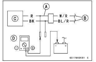


Main Harness [B] Primary Fuel Injector #1 [C]
Special Tool - Measuring Adapter: 57001-1700

Primary Fuel Injector Power Source Voltage Connections to Adapter:
For Primary Fuel Injector #1, #2, #3, #4
Digital Meter (+) → R (injector W/R) lead
Digital Meter (–) → Battery (–) terminal
Power Source Voltage Standard: Battery Voltage for 3 seconds, and then 0 V
If the reading stays on battery voltage and never shows 0 V, check the fuel pump relay (see Relay Circuit Inspection in the Electrical System chapter).
If the fuel pump relay is normal, check the ECU for its ground and power supply (see ECU Power Supply Inspection).
If the ground and power supply are good, replace the ECU (see ECU Removal/Installation).
If there is still no battery voltage, check the fuel pump relay (see Relay Circuit Inspection in the Electrical System chapter).
If the ground and power supply are good, replace the ECU (see ECU Removal/Installation).
If there is still no battery voltage, check the fuel pump relay (see Relay Circuit Inspection in the Electrical System chapter).
If the fuel pump relay is normal, check the power source wiring (see wiring diagram in this section).
Special Tool - Hand Tester: 57001-1394
If the wiring is good, check the ECU for its ground and power supply (see ECU Power Supply Inspection).
If the ground and power supply are good, replace the ECU (see ECU Removal/Installation).
If the reading is in specification, check the output voltage (see Fuel Injector Output Voltage Inspection).
 Fuel Injector Power Source
Voltage Inspection
 For Secondary Fuel Injectors
Inner Tube Inspection
Visually inspect the inner tube [A].
If there is any damage, replace the inner tube. Since
damage to the inner tube damages the oil seal, replace
the oil seal whenever the inner tube is replaced.
NOTICE
If the inner tube is badly bent or creased, replace
it. Excessive bending, followed by ...
Rear Fender Front Installation
Installation is the reverse of removal. Note the following.
Run the harness, cables and leads correctly (see Cable,
Wire, and Hose Routing section in the Appendix chapter).
When installing the clamp [A] on the rear fender front [B],
install it so that the clamp positions at near the ...
Rear Turn Signal Light Bulb Replacement
Remove the upper seat cover (see Seat Cover Removal
in the Frame chapter).
Disconnect the tail/brake light connector [A].
Turn the socket [A] counterclockwise and remove the
socket together with the bulb.
Push and turn the turn signal light bulb [A] counterclockwise
an ...