
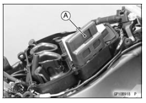
The IC igniter is built in the ECU [A].
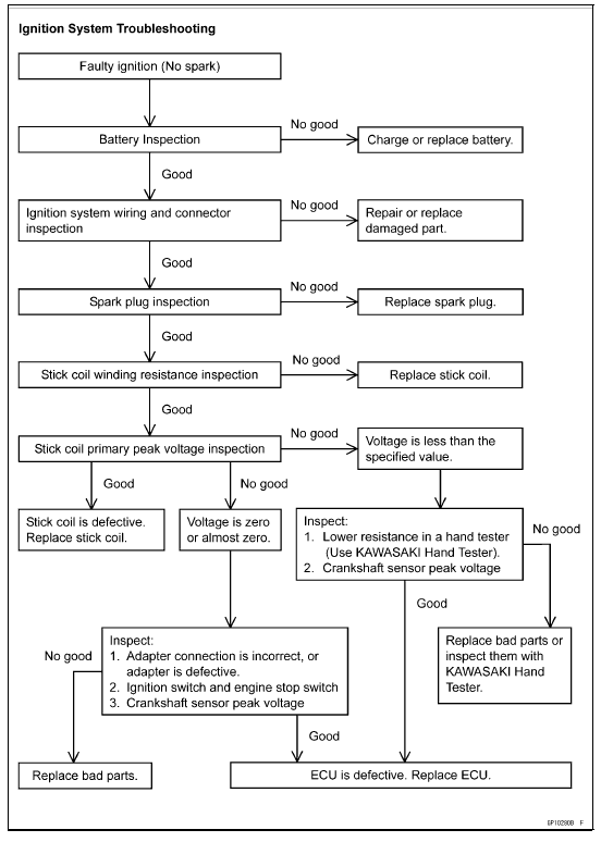
Interlock Operation Inspection (see Interlock Operation Inspection) Ignition System Troubleshooting (see Ignition System section) ECU Power Supply Inspection (see ECU Power Supply Inspection in the Fuel System (DFI) chapter)
Ignition System Circuit
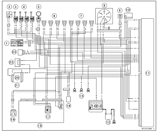
1. Ignition Switch
2. Engine Stop Switch
3. Stick Coils
4. Spark Plugs
5. Crankshaft Sensor
6. Primary Fuel Injectors
7. Secondary Fuel Injectors
8. Gear Position Switch
9. Sidestand Switch
10. Joint Connector E
11. ECU
12. Battery
13. Main Fuse 30 A
14. ECU Fuse 15 A
15. Frame Grounds
16. Fuel Pump
17. Fuel Pump Relay
18. Relay Box
19. Starter Lockout Switch
20. Ignition Fuse 15 A
21. Fuse Box 1
22. Joint Connector F
23. Vehicle-down Sensor
 Interlock Operation Inspection
Starter Clutch Removal
Remove:
Torque Limiter (see Torque Limiter Removal)
Transmission Assy (see Transmission Assy Removal)
Starter Clutch Shaft Holder Bolt [A]
Starter Clutch Shaft Bolt [B]
Starter Clutch Shaft Holder [C]
Remove the starter clutch shaft [A] using a suitable M8
bolt [B].
Take ...
Radiator Fan System
Fan Motor Inspection
Remove the air cleaner housing (see Air Cleaner Housing
Removal in the Fuel System (DFI) chapter).
Disconnect the connector [A].
Using an auxiliary leads, supply battery power to the fan
motor.
If the fan does not rotate, the fan motor is defective and
must be re ...
Tire Air Pressure Inspection
Remove the air valve cap.
Measure the tire air pressure with an air pressure gauge
[A] when the tires are cold (that is, when the motorcycle
has not been ridden more than a mile during the past 3
hours).
Install the air valve cap.
Adjust the tire air pressure according to the specifi ...
