

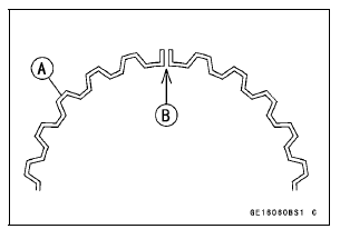
Spread the rail with your thumbs, but only enough to fit the rail over the piston.
Release the rail into the bottom piston ring groove.
NOTE
The oil ring rails have no “top” or “bottom”.
NOTE
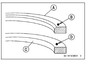
Do not mix up the top and second ring.
NOTE
If a new piston is used, use new piston rings.
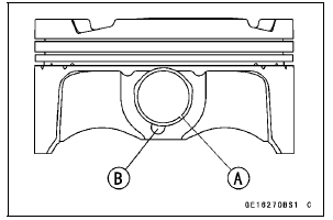
When installing the piston pin snap ring, compress it only enough to install it and no more.
NOTICE
Do not reuse snap rings, as removal weakens and deforms them. They could fall out and score the cylinder wall.
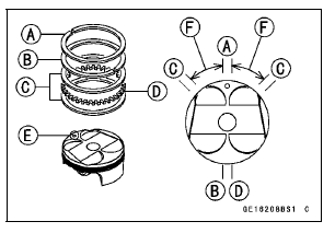
 40° of angle from the
Top Ring [A]
Second Ring [B]
Oil Ring Steel Rails [C]
Oil Ring Expander [D]
Hollow [E]
30  40° [F]
Special Tools - Piston Ring Compressor Grip: 57001-1095
Piston Ring Compressor Belt,  67
67

 79:
79:
57001-1097
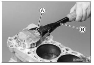
 Piston Removal
 Cylinder (Upper Crankcase) Wear Inspection
Valve-to-Guide Clearance Measurement (Wobble Method)
If a small bore gauge is not available, inspect the valve
guide wear by measuring the valve to valve guide clearance
with the wobble method as indicated below.
Insert a new valve [A] into the guide [B] and set a dial
gauge against the stem perpendicular to it as close as
possible to the cy ...
Check 3-3: High Beam Indicator Light (LED) Inspection
Connect the leads in the same circuit as Check 3-2.
Connect the terminal [7] to the battery (+) terminal.
Check that the high beam indicator light (LED) [A] goes
on.
If the indicator light does not go on, replace the meter unit.
...
For Primary Fuel Injectors
Remove the air cleaner housing (see Air Cleaner Housing
Removal).
Disconnect the injector connector and connect the harness
adapter [A] between these connectors as shown in
the figure.
Main Harness [B]
Primary Fuel Injector #1 [C]
Special Tool - Measuring Adapter: 57001-1700
...