
NOTE
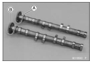
The exhaust camshaft has a 1001 EX mark [A] and the intake camshaft has a 3154 IN mark [B]. Be careful not to mix up these shafts.
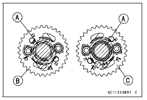
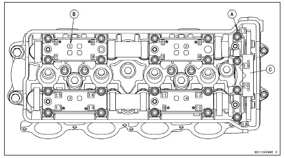
#4 Cam Positions [A] Intake Camshaft Sprocket [B] Exhaust Camshaft Sprocket [C]
The intake camshaft sprocket and exhaust camshaft sprocket are identical
Torque - Camshaft Sprocket Bolts: 15 N·m (1.5 kgf·m, 11 ft·lb)
If a new camshaft is to be used, apply a thin coat of molybdenum disulfide grease to the cam surfaces.
NOTICE
The crankshaft may be turned while the camshafts are removed. Always pull the chain taut while turning the crankshaft. This avoids kinking the chain on the lower (crankshaft) sprocket. A kinked chain could damage both the chain and the sprocket.
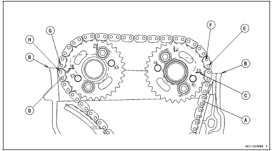
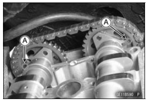
The timing marks must be aligned with the cylinder head upper surface [B].
EX Mark [C] IN Mark [D] #1 Pin [E] #2 Pin [F] #28 Pin [G] #29 Pin [H]
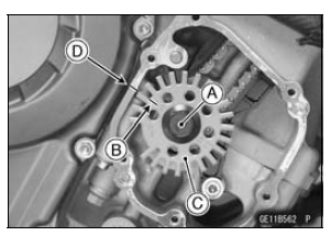
[B] and upper camshaft chain guide [C].
Torque - Camshaft Cap Bolts (1 ∼ 18): 12 N·m (1.2 kgf·m, 106 in·lb) Upper Camshaft Chain Guide Bolts (19, 20): 12 N·m (1.2 kgf·m, 106 in·lb)
 Camshaft Removal
 Camshaft, Camshaft Cap Wear Inspection
Idle Speed Control Valve Actuator Installation
Replace the O-ring [A] with a new one.
Apply engine oil to the new O-ring.
Install the idle speed control valve [A] as shown in the
figure.
10° [B]
Tighten:
Torque - Idle Speed Control Valve Actuator Retainer
Screws: 2.06 N·m (0.21 kgf·m, 18 in·lb)
Install th ...
Front Fork Oil Change
Remove the front fork (see Front Fork Removal (Each
Fork Leg)).
Turn the spring preload adjuster fully counterclockwise for
removing the piston rod assy easily.
Hold the inner tube lower end in a vise.
Using the wrench [A], unscrew the top plug [B] out of the
outer tube.
Special Too ...
Electrical Wiring
Wiring Inspection
Visually inspect the wiring for signs of burning, fraying,
etc.
If any wiring is poor, replace the damaged wiring.
Pull each connector [A] apart and inspect it for corrosion,
dirt, and damage.
If the connector is corroded or dirty, clean it carefully. If it
is da ...