
NOTE
Use the battery which is fully charged.
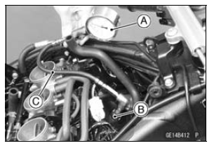
Special Tools - Compression Gauge, 20 kgf/cm²: 57001-221 Compression Gauge Adapter, M10 × 1.0: 57001-1601 L-Shape Hose [C]: 57001-1606
Cylinder Compression
Usable Range: 1 099  1 668 kPa (11.2
 17.0 kgf/cm²,
159  242 psi) at 320 r/min (rpm)
The following table should be consulted if the obtainable compression reading is not within the usable range.
| Problem | Diagnosis | Remedy (Action) |
| Cylinder compression is higher than usable range | Carbon accumulation on piston and in combustion chamber possibly due to damaged valve stem oil seal and/or damaged piston oil rings (This may be indicated by white exhaust smoke). | Remove the carbon deposits and replace damaged parts if necessary. |
| Incorrect cylinder head gasket thickness | Replace the gasket with a standard part. | |
| Cylinder compression is lower than usable range | Gas leakage around cylinder head | Replace damaged gasket and check cylinder head warp |
| Bad condition of valve seating | Repair if necessary. | |
| Incorrect valve clearance | Adjust the valve clearance. | |
| Incorrect piston/cylinder clearance | Replace the piston and/or cylinder. | |
| Piston seizure | Inspect the cylinder and replace/repair the cylinder and/or piston as necessary. | |
| Bad condition of piston ring and/or piston ring grooves | Replace the piston and/or the piston rings. |
 Cylinder Head
 Cylinder Head Removal
Battery Installation
Place the battery in the battery case.
Connect the (+) cable to the (+) terminal,
and then connect the (–) cable
to the (–) terminal.
NOTICE
Installing the (–) cable to the (+)
terminal of the battery or the (+)
cable to the (–) terminal of the
battery can seriously damaged
...
Master Cylinder Rubber Parts Replacement
Front Master Cylinder Disassembly
Remove the front master cylinder (see Front Master Cylinder
Removal in the Brakes chapter).
Remove the seal cover [A], circlip [B], connector [C] and
O-ring [D].
Special Tool - Inside Circlip Pliers: 57001-143
Unscrew the locknut [E] and pivot bolt ...
Stick Coil Inspection
Remove the stick coils (see Stick Coil Removal).
Measure the primary winding resistance [A] as follows.
Connect the hand tester between the coil terminals.
Set the tester to the × 1 Ω range, and read the tester.
Measure the secondary winding resistance [B] as follows.
Conn ...