
NOTICE
Do not turn the compression damping force adjuster beyond the fully seated position or the adjusting mechanism may be damaged.
A. Compression Damping Force Adjuster for High Speed
B. To increase damping force
C. To decrease damping force
Compression Damping Force Setting for High and Low Speeds
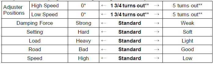
*: This position is the fully seated position (turned fully clockwise).
**: Out from the fully seated position (turned fully clockwise). This adjustment range may not exactly match the number shown in the table due to small tolerance of production.
The standard suspension setting positions are as follows:
Standard Setting Position (Rear Shock Absorber)
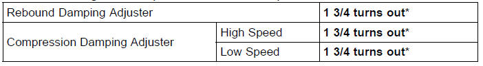
*: Out from the fully seated position (turned fully clockwise)
 Compression Damping Force Adjustment
 Wheels
Clutch Cover Assembly
Replace the needle bearings and oil seal with new ones.
NOTE
Install the needle bearings so that the manufacture’s
mark face out.
Install the needle bearings [A] and oil seal [B] position as
shown in the figure.
Press the upper and lower bearings so that the bearing
surface [ ...
Piston Ring End Gap Inspection
Place the piston ring [A] inside the cylinder (upper
crankcase), using the piston to locate the ring squarely
in place. Set it close to the bottom of the cylinder, where
cylinder wear is low.
Measure the gap [B] between the ends of the ring with a
thickness gauge.
Piston Ring End Gap ...
Alternator Rotor Installation
Using a cleaning fluid, clean off any oil or dirt on the following
portions and dry them with a clean cloth.
Crankshaft Tapered Portion [A]
Alternator Rotor Tapered Portion [B]
Install the alternator rotor.
Using a cleaning fluid, clean off any oil or dirt on the
washer [A] ...