
The brightness of the tachometer LED segments and illumination of the multifunction meter are controlled automatically depending on the ambient brightness.
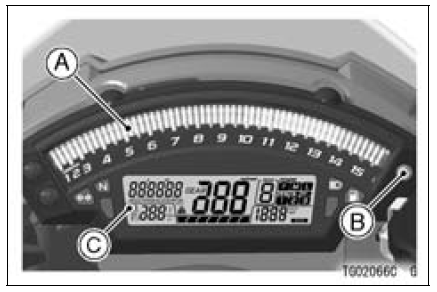
A. Tachometer
B. Ambient Brightness Sensor
C. Multifunction Meter
NOTE
Be careful not to cover the ambient brightness sensor on the meter instrument while riding the motorcycle.
Instrument Display Brightness Adjustment
The brightness of the instrument display can be adjusted manually in three levels while the motorcycle is at a stop.
The tachometer now operates normally.
 Tachometer
 Multifunction Meter
Fuel Tank
The following octane rating gasoline
is recommended for the fuel tank.
Avoid filling the tank in the rain or where
heavy dust is blowing so that the fuel
does not get contaminated.
A. Tank Cap
B. Fuel Tank
C. Top Level
D. Filler Neck
WARNINGGasoline is extremely flammable
an ...
For Secondary Fuel Injectors
Remove the fuel tank (see Fuel Tank Removal).
Disconnect the secondary fuel injector connector [A].
Connect a digitalmeter to the terminals in each secondary
fuel injector [A].
Measure the secondary fuel injector resistance.
Secondary Fuel Injector Resistance
Standard: Abo ...
Engine Oil Change
Situate the motorcycle so that it is vertical after warming
up the engine.
Remove the engine oil drain bolt [A] to drain the oil.
The oil in the oil filter can be drained by removing the filter
(see Oil Filter Replacement).
Replace the drain bolt gasket [B] with a new one.
Tighten t ...