
KIBS Hydraulic Unit Communication Line Inspection
When the data (for status of KIBS hydraulic unit) is not sent from the KIBS hydraulic unit to the meter unit and ECU, the service code 1b is displayed.
The data is sent through the CAN communication line.
The service code 1b is detected with the meter unit.
The FI symbol does not appear in this error code.
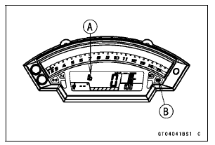
When the service code 1b [A] is detected, the ABS indicator light (LED) [B] goes on and the code of 1b displayed on the LCD.

Special Tool - Hand Tester: 57001-1394
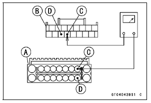
Wiring Inspection KIBS Hydraulic Unit Connector [A] ←→ Meter Unit Connector [B] GY/BL lead (KIBS Hydraulic Unit terminal 2) [C] LB lead (KIBS Hydraulic Unit terminal 11) [D]

If the wiring is good, replace the KIBS hydraulic unit (see KIBS Hydraulic Unit Removal/Installation in the Brakes chapter).
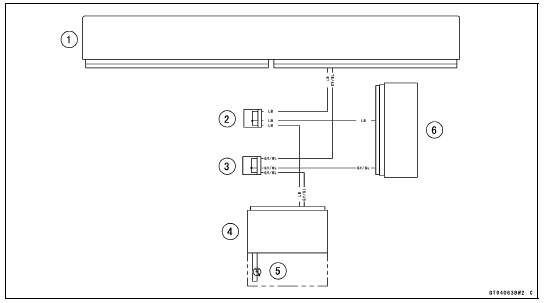
KIBS Hydraulic Unit Communication Line Circuit

1. ECU
2. Joint Connector D
3. Joint Connector C
4. Meter Unit
5. ABS Indicator Light (LED)
6. KIBS Hydraulic Unit
 Oxygen Sensor Heater Power Source Voltage Inspection
Alternator Inspection
There are three types of alternator failures: short, open
(wire burned out), or loss in rotor magnetism. A short or
open in one of the coil wires will result in either a low output,
or no output at all. A loss in rotor magnetism, which may be
caused by dropping or hitting the alternator, by leav ...
Coupling Bearing Removal
Remove:
Coupling
Grease Seal
Circlip [A]
Special Tool - Inside Circlip Pliers: 57001-143
Remove the bearing [A] by tapping from the wheel side.
Special Tool - Bearing Driver Set [B]: 57001-1129
...
Gear Position Switch Output Voltage Inspection
NOTE
Be sure the battery is fully charged.
Turn the ignition switch to OFF.
Remove the fuel tank (see Fuel Tank Removal in the Fuel
System (DFI) chapter).
Disconnect the sidestand switch/gear position switch lead
connector [A].
Connect the measuring adapter [A] between the ...