
Check 1-1: Switching Inspection
The all LCD segments [A] appear for 3 seconds.
The warning indicator light (Red LED) [B] goes on for 3 seconds and then goes off in a moment after that goes off.
The warning indicator light (Yellow LED) [C] goes on for 3 seconds.
The fuel level (ZX1000J model) or ABS (ZX1000K model) warning indicator light (LED) [D] goes on.
The tachometer (LED) [E] blinks 3 times.
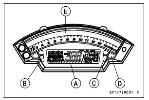
If the meter does not work, replace the meter unit.
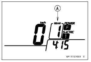
This display is ordinary indication.
If the meter does not work, replace the meter unit.
If meter does not work, replace the meter unit.
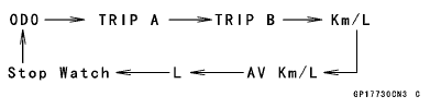
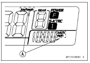
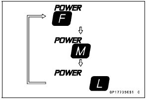
Normal Mode [A] Race Mode [B]
NOTE
Mile/Km Display can alternate between English and metric modes (mile and km) in the digital meter. Make sure that km or mile according to local regulations is correctly displayed before riding.
If the display function does not work, replace the meter unit.
If the indicator symbol does not work, check the following parts.
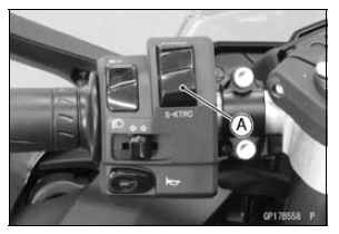
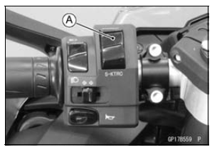
S-KTRC Button (see Switch Inspection) Wiring (see Meter Unit Circuit)
If the above parts is good, replace the meter unit and/or ECU.
If the display function does not work, check the following parts.
Power Mode Button (see Switch Inspection) Wiring (see Meter Unit Circuit)
If the above parts is good, replace the meter unit and/or ECU.
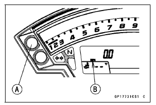
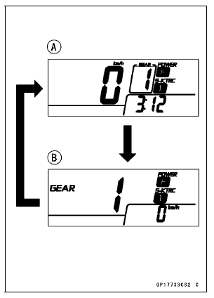
Check 1-2: Gear Position Indication Inspection
The neutral indicator light (LED) [A] goes on when the transmission gear is neutral position.
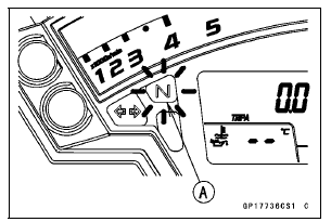
(This illustration shows normal mode.)
If the display function does not work, check the following parts.
Gear Position Switch (see Gear Position Switch Inspection) Wiring (see Meter Unit Circuit)
If the above parts is good, replace the meter unit and/or ECU.
 Meter Unit Removal/Installation
Fuses
Fuses are arranged in the fuse boxes
located under the passenger’s seat and
in the left fairing. The main fuse is
located under the passenger’s seat.
If a fuse fails during operation, inspect
the electrical system to determine
the cause, and then replace it with
a new fuse of proper amp ...
Check 3-7 Stop Watch Inspection
Connect the leads in the same circuit as Check 3-2.
By pushing the upper button each time to set the stop
watch mode.
Connect the insulated auxiliary lead processed insulation
to the terminal [13] as shown in the figure, then stop watch
start to count.
While count the stop watch, conn ...
Service Code Erasing
When repair has been done, warning indicator light (LED) and warning symbol
go off and service
code are not displayed.
But the service codes stored in memory of the ECU are not erased to preserve
the problem history.
In this model, the problem history can not be erased. However, the memorie ...
