
If the fuel pump relay is normal, check the wiring to the fuel pump relay (see Fuel Pump Relay Circuit).
Special Tool - Hand Tester: 57001-1394
If the wiring is good, check the ECU for its ground and power supply (see ECU Power Supply Inspection in the Fuel System (DFI) chapter).
If the ground and power supply are good, replace the ECU (see ECU Removal/Installation in the Fuel System (DFI) chapter).
Fuel Pump Relay Circuit
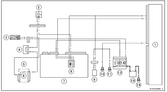
1. ECU
2. Engine Stop Switch
3. Ignition Switch
4. Joint Connector F
5. Fuse Box 1
6. Ignition Fuse 15 A
7. Relay Box
8. Fuel Pump Relay
9. Fuel Pump
10. Frame Ground 1
11. Frame Ground 3
12. Starter Relay
13. ECU Fuse 15 A
14. Main Fuse 30 A
15. Battery
16. Engine Ground
Stick Coil #1: Service Code 51
Stick Coil #2: Service Code 52
Stick Coil #3: Service Code 53
Stick Coil #4: Service Code 54
 Fuel Pump Relay Removal/Installation
Service Code Reading
The service code(s) is displayed on the LCD by the number
of two digits.
NOTE
The service code of the KIBS and ABS adds “b” at the
left side of the code.
The service code of the ESD adds “E” at the left side of
the code.
When there are a number of problems, all the serv ...
Regulator/Rectifier Inspection
Remove:
Upper Fairing Assembly (see Upper Fairing Assembly
Removal in the Frame chapter)
Right Inner Fairing (see Inner Fairing Removal in the
Frame chapter)
Bolts [A]
Regulator/Rectifier [B]
Set the hand tester to the × 1 kΩ range and make the
measurements show ...
Air Suction Valve Inspection
Remove the air suction valve (see Air Suction Valve Removal).
Visually inspect the reeds [A] for cracks, folds, warps,
heat damage or other damage.
If there is any doubt as to the condition of the reeds, replace
the air suction valve as an assembly.
Check the reed contact areas [B] of ...
