
There is an adjuster on the brake lever. The adjuster has 6 positions so that the released lever position can be adjusted to suit the operator’s hands.
Push the lever forward and turn the adjuster to align the number with the mark on the lever holder. The distance from the grip to the released lever is minimum at Number 6 and maximum at Number 1.
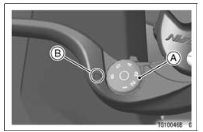
A. Adjuster
B. Mark
 Starter Button
 Fuel Tank Cap
Clutch Cover Installation
Using a cleaning fluid, clean off any oil or dirt that may
be on the silicone sealant coating area. Dry them with a
clean cloth.
Apply silicone sealant to the area [A] where the mating
surface of the crankcase touches the clutch cover gasket.
Sealant - Liquid Gasket, TB1211F: 92104-000 ...
Radiator and Radiator Fan Removal
Remove:
Upper Fairing Assembly (see Upper Fairing Assembly
Removal in the Frame chapter)
Coolant (Drain, see Coolant Change in the Periodic
Maintenance chapter)
Air Cleaner Housing (see Air Cleaner Housing Removal
in the Fuel System (DFI) chapter)
Coolant Reserve Tank (see Coolant R ...
Model Identification
ZX1000JB (US and CA Models) Left Side View
ZX1000JB (US and CA Models) Right Side View
ZX1000JB (EUR Models) Left Side View
ZX1000JB (EUR Models) Right Side View
ZX1000KB (US and CA Models) Left Side View
ZX1000KB (US and CA Models) Right Side View
ZX1000KB (EUR Models) ...