
Make sure that the groove on the shaft is pointing toward the center of the screw [D].
If the shaft position is incorrect, refer to the following NOTE and procedures to electrically adjust the shaft position.
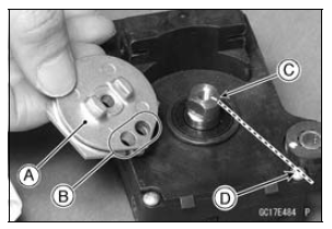
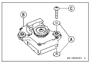
Torque - Exhaust Butterfly Valve Actuator Pulley Bolt: 4.9 N·m (0.50 kgf·m, 43 in·lb)
NOTICE
If the pulley bolt is tightened without holding, the actuator damage will occur.
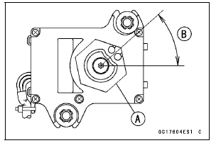
41.7° ±7° [B]
This position is original position of the pulley.
NOTE
Correct the position electrically after confirming the use is discontinued and there is no damage when differing from the angle of shown in the figure.
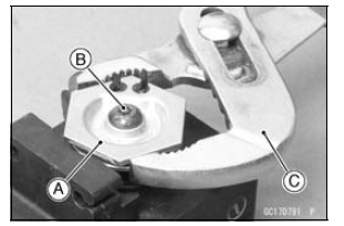
NOTICE
Do not correct the pulley position with the tool, forcibly. The actuator damage will occur.
If the pulley angle is wrong, adjust the angle as follows.
Connect: 2 pins Connector 3 pins Connector
Turn the ignition switch to ON.
Confirm the pulley turns clockwise or counterclockwise then it stops at the original position.
If the pulley position has not been returned to the original position, electrically adjust the shaft position as follows.
Remove: 2 pins Connector 3 pins Connector
Turn the pulley to the original position by turning it clockwise or counterclockwise by connecting the battery to the 2 pin connector terminals. To turn the pulley gradually, intermittently connect the battery positive (+) terminal to the 2 pin connector terminal while connecting the battery negative (–) terminal to the connector.
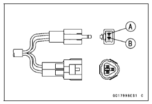
Pink (–) lead terminal [A] Gray (+) lead terminal [B]
Clockwise: Pink (–) lead terminal to battery (–) terminal Gray (+) lead terminal to battery (+) terminal
Counterclockwise: Pink (–) lead terminal to battery (+) terminal Gray (+) lead terminal to battery (–) terminal
Reconnect the 2 pins connector and 3 pins connector, and turn the ignition switch ON.
Make sure that the pulley turns clockwise and then counterclockwise.
The pulley should returns to the original position.
Turn the ignition switch OFF.
If the pulley does not return to the original position, check the exhaust butterfly valve actuator resistance (see Exhaust Butterfly Valve Actuator Resistance Inspection).
 Exhaust Butterfly Valve Actuator Removal
 Exhaust Butterfly Valve Actuator Inspection
Spring Tension Inspection
Since a spring becomes shorter as it weakens, check its
free length [A] to determine its condition.
If the spring of either fork leg is shorter than the service
limit, it must be replaced. If the length of a replacement
spring and that of the remaining spring vary greatly, the
remaining s ...
Engine Stop Switch Operation Inspection
First Step
Set the gear position in the neutral position.
Turn the ignition switch to ON.
Turn the engine stop switch to stop position [A].
Push the starter button.
The engine does not start.
If the engine starts, inspect the engine stop switch (see
Switch Inspection in the Electri ...
Oil Filter Replacement
Drain the engine oil (see Engine Oil Change).
Remove the left lower fairing (see Lower Fairing Removal
in the Frame chapter).
Remove the oil filter [A] with the oil filter wrench [B].
Special Tool - Oil Filter Wrench: 57001-1249
Replace the filter with a new one.
Apply grease t ...