
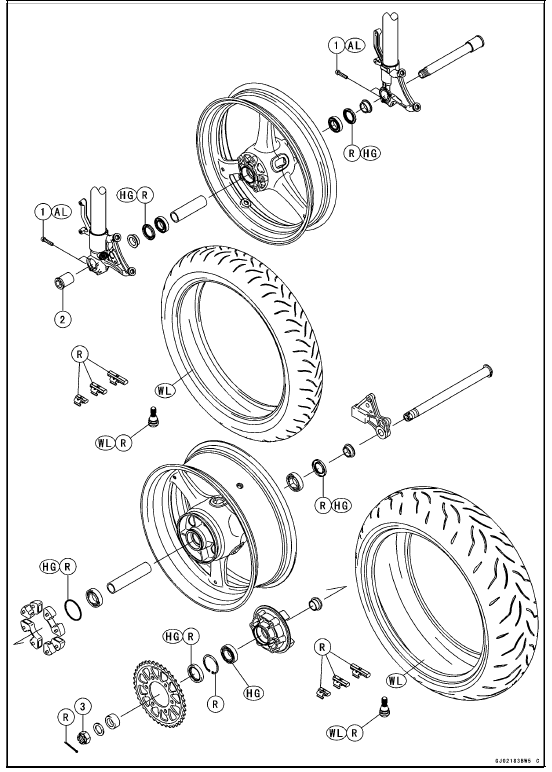

AL: Tighten the two clamp bolts alternately two times to ensure even tightening torque.
HG: Apply high-temperature grease.
R: Replacement Parts WL: Apply soap and water solution or rubber lubricant.
Specifications
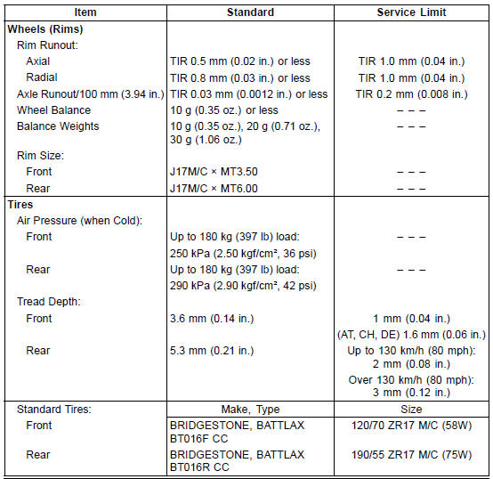
| WARNING Some replacement tires may adversely affect handling and cause an accident resulting in serious injury or death. To ensure proper handling and stability, use only the recommended standard tires for replacement, inflated to the standard pressure. |
 Wheels/Tires
 Special Tools
Spring Plate Free Play Measurement
Insufficient clutch free play will cause the engine braking
effect to be more sudden, resulting in rear wheel hop. On
the other hand, if the free play is excessive, the clutch lever
may feel “spongy� or pulsate when pulled.
Hold an extra drive shaft in a vise and install the following
c ...
Air Intake Duct Assembly (Other than US, CA and CAL Models)
Install the seals [A] as shown in the figure.
Fit the projections [A] of the air intake valve to the hole [B]
of the air intake ducts.
Tighten:
Torque - Air Intake Duct Assembly Screws: 1.5 N·m (0.15
kgf·m, 13 in·lb)
Hang the shaft [A] to the air intake valve securely ...
Clutch Cover Assembly
Replace the needle bearings and oil seal with new ones.
NOTE
Install the needle bearings so that the manufacture’s
mark face out.
Install the needle bearings [A] and oil seal [B] position as
shown in the figure.
Press the upper and lower bearings so that the bearing
surface [ ...