
This motorcycle has a combination key, which is used for the ignition switch, steering lock, seat lock, and fuel tank cap.
Included with the key is a key number, which may be stamped on a separate plate. Record the key number in the space provided and store the number in a safe place. If your keys came with a plate, store it in a safe place as well.
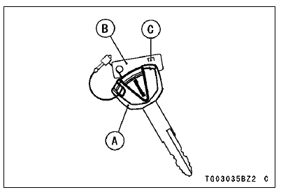
A. Ignition Key
B. Tag
C. Key Number
Write your key number here
In the event you lose your keys, you will need the key number to have a duplicate made. If you cannot locate your key number, contact the dealer where you purchased your Kawasaki motorcycle.
It’s possible the dealermay have the number in its records. If the key number is lost completely, you will need to replace the ignition switch and all other locks operated by that key.
Contact your Kawasaki dealer to purchase additional spare keys either using your original key as a master or using the key code on the tag or your key.
Store one key at home and keep another spare in your wallet or riding gear, in case the original is lost.
 S-KTRC Level Indicator
 Ignition Switch/Steering Lock
Front Fork Oil Change
Remove the front fork (see Front Fork Removal (Each
Fork Leg)).
Turn the spring preload adjuster fully counterclockwise for
removing the piston rod assy easily.
Hold the inner tube lower end in a vise.
Using the wrench [A], unscrew the top plug [B] out of the
outer tube.
Special Too ...
Starter Clutch Installation
Replace the O-ring [A] with a new one and apply grease.
Apply molybdenum disulfide grease to the starter clutch
shaft [B].
Install:
Starter Clutch [C]
Spacer (Small Diameter) [D]
Spacer (Large Diameter) [E]
Starter Clutch Shaft
Starter Clutch Shaft Holder [F]
Turn the O-ring si ...
Windshield and Other Plastic Parts
After washing use a soft cloth to
gently dry plastic parts. When dry,
treat the windshield, headlight lens,
and other nonpainted plastic parts with
an approved plastic cleaner/polisher
product.
NOTICE
Plastic parts may deteriorate
and break if they come in contact
with chemical substances
...