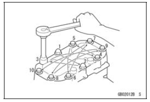

Generally, when installing a part with several bolts, nuts, or screws, start them all in their holes and tighten them to a snug fit. Then tighten them according to the specified sequence to prevent case warpage or deformation which can lead to malfunction. Conversely when loosening the bolts, nuts, or screws, first loosen all of them by about a quarter turn and then remove them. If the specified tightening sequence is not indicated, tighten the fasteners alternating diagonally.

Tightening Torque
Incorrect torque applied to a bolt, nut, or screw may lead to serious damage. Tighten fasteners to the specified torque using a good quality torque wrench.

 Replacement Parts
 Force
ForceDrive Chain Slack Inspection
Refer to the Drive Chain Slack Inspection in the Periodic
Maintenance chapter.
Drive Chain Slack Adjustment
Refer to the Drive Chain Slack Adjustment in the Periodic
Maintenance chapter.
Wheel Alignment Inspection/Adjustment
Refer to the Wheel Alignment Inspection in the Periodic
Maintenance ...
Alternator Cover Removal
Remove:
Upper Fairing Assembly (see Upper Fairing Assembly
Removal in the Frame chapter)
Air Cleaner Housing (see Air Cleaner Housing Removal
in the Fuel System (DFI) chapter)
Bolt [A]
Bring the heat insulator plate [B] forward to remove the
alternator lead connector.
Clear the p ...
Technical Information - Electronic Steering Damper (ESD/ZX1000JD/KD models)
1) Overview
This model has an Electronic Steering Damper (ESD)
[A]. Unlike conventional manual adjustment method of
Kawasaki, damping characteristics are adjusted by the
electronic control unit.
2) Purpose
Designed to offer increased stability at high speed without interfering with
light ...