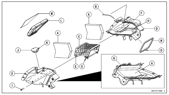

Projections [E] and Holes [F] Grooves [G] and Ribs [H]
Torque - Air Intake Duct Assembly Screws [I]: 1.5 N·m (0.15 kgf·m, 13 in·lb)

 Air Intake Duct Disassembly (US, CA and CAL Models)
 Air Intake Duct Disassembly
(Other than US, CA and CAL Models)
Air Intake Duct Disassembly
(Other than US, CA and CAL Models)Idle Speed Control Valve Actuator Resistance Inspection
Turn the ignition switch to OFF.
Remove the air cleaner housing (see Air Cleaner Housing
Removal in the Fuel System (DFI) chapter).
Disconnect the idle speed control valve actuator connector
[A].
Connect a digital meter to the idle speed control valve
actuator connector [A]
...
Stopping the engine
Close the throttle completely.
Shift the transmission into neutral
Turn the ignition key to “OFF”.
Support the motorcycle on a firm,
level surface with the side stand.
Lock the steering.
NOTE
The motorcycle is equipped with a
vehicle-down sensor, which causes
the engine to sto ...
Exploded View
CL: Apply cable lubricant.
EO: Apply engine oil.
G: Apply grease.
HG: Apply high-temperature grease.
L: Apply a non-permanent locking agent.
M: Apply molybdenum disulfide grease.
R: Replacement Parts
S: Follow the specified tightening sequence.
Specifications
Special ...