
If it does, discard it.
| WARNING Unbalanced wheels can create an unsafe riding condition. If the balance weight has any play on the rib of the rim, the blade and/or clip have been stretched. Replace the loose balance weight. Do not reuse used balance weight. |
Balance Weight 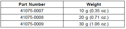
NOTE
An imbalance of less than 10 grams (0.35 oz.) will not usually affect running stability.
Slip the balance weight [A] onto the rib [B] by pushing or lightly hammering [C] the clip [D].
Left Side [E] Right Side [F]
Be sure to install the balance weight.
Check that the blade [A] and clip [B] are fully seated on the rim [C] and that the clip is hooked over the rib [D].
Left Side [E] Right Side [F]
 Balance Weight Removal
 Tires
TiresOil Pressure Measurement
Remove:
Right Lower Fairing (see Lower Fairing Removal in the
Frame chapter)
Oil Passage Plug [A]
Attach the adapter [A] and gauge [B] to the plug hole.
Special Tools - Oil Pressure Gauge, 10 kgf/cm²: 57001-164
Oil Pressure Gauge Adapter, PT3/8: 57001
-1233
...
Crankshaft Sensor Removal
Remove:
Fuel Tank (see Fuel Tank Removal in the Fuel System
(DFI) chapter)
Crankshaft Sensor Lead Connector [A]
Remove:
Right Lower Fairing (see Lower Fairing Removal in the
Frame chapter)
Bolts [A]
Crankshaft Sensor Cover [B] and Gasket
Oil Pressure Switch Terminal [C]
...
Meter Unit Removal/Installation
Remove the upper fairing assembly (see Upper Fairing
Assembly Removal in the Frame chapter)
Remove the bolt [A] (other than US, CA and CALmodels).
Slide back the dust cover and disconnect the meter unit
connector [B].
Remove:
Bolts [A]
Nut [B] (other than US, CA and CAL mode ...