
NOTE
The battery is different in the model equipped with KIBS and the model without KIBS. The (+) terminal and (–) terminal are right and left reversed.
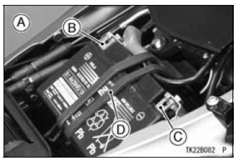
A. For models equipped with KIBS
B. (+) Terminal
C. (–) Terminal
D. Rubber Band
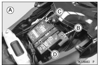
A. For models without KIBS
B. (+) Terminal
C. (–) Terminal
D. Rubber Band
 Battery Charging
 Battery Installation
Throttle Body Assy Installation
Apply a thin coat of grease to the throttle cable lower ends.
Fit the accelerator cable end [A] and the decelerator cable
end [B] into the throttle pulley.
Install the clamp [C] securely.
Install the throttle body assy holder clamp bolt heads [A]
outside as shown in the figure.
...
Operating Procedures
Clean the seat area carefully.
Coat the seat with machinist’s dye.
Fit a 45° cutter into the holder and slide it into the valve
guide.
Press down lightly on the handle and turn it right or left.
Grind the seating surface only until it is smooth.
NOTICE
Do not grind the seat too ...
Brake Hose and Pipe Damage and Installation Condition Inspection
Inspect the brake hoses, pipes and fittings for deterioration,
cracks and signs of leakage.
The high pressure inside the brake line can cause fluid to
leak [A] or the hose to burst if the line is not properly maintained.
Bend and twist the rubber hose while examining
it.
Replace the ...