
The first 1 600 km (1 000 mi) that the motorcycle is ridden is designated as the break-in period. If the motorcycle is not used carefully during this period, you may very well end up with a “broken down” instead of a “broken in” motorcycle after a few thousand kilometers.
The following rules should be observed during the break-in period.
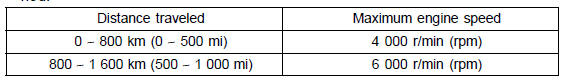
NOTE
When operating on public roadways, keep maximum speed under traffic low limits.
| WARNING New tires are slippery and may cause loss of control and injury. A break-in period of 160 km (100 miles) is necessary to establish normal tire traction. During break-in, avoid sudden and maximum braking and acceleration, and hard cornering. |
In addition to the above, at 1 000 km (600 mi) it is extremely important that the owner has the initial maintenance service performed by a competent mechanic following the procedures in the Service Manual.
 Front Footpeg Position
Intake Air Temperature Sensor Removal
NOTICE
Never drop the intake air temperature sensor especially
on a hard surface. Such a shock to the sensor
can damage it.
Remove the fuel tank (see Fuel Tank Removal in the Fuel
System (DFI) chapter).
Disconnect the connector [A] from the intake air temperature
sensor.
Remove the da ...
Exploded View
HG: Apply high-temperature grease.
HO: Apply heavy oil.
L: Apply a non-permanent locking agent.
MO: Apply molybdenum disulfide oil solution.
(mixture of the engine oil and molybdenum disulfide grease in a weight ratio
10:1)
R: Replacement Parts
Specifications
Special Too ...
Coolant Level Inspection
NOTE
Check the level when the engine is cold (room or ambient
temperature).
Check the coolant level in the reserve tank [A] with the
motorcycle held perpendicular (Do not use the sidestand).
If the coolant level is lower than the “L” level line [B], remove
the upper fairing assembly (s ...
