
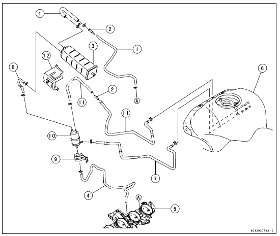
1. Green Hoses (Purge)
2. Fittings
3. Canister
4. White Hose (Vacuum)
5. Throttle Body Assy
6. Fuel Tank
7.Red Hose (Return)
8. Blue Hose (Breather)
9. Bracket (for Separator)
10. Separator
11. Blue Hoses (Breather)
12. Bracket (for Canister)
 Separator Operation Test
 Cooling System
Engine Oil Change
Situate the motorcycle so that it is vertical after warming
up the engine.
Remove the engine oil drain bolt [A] to drain the oil.
The oil in the oil filter can be drained by removing the filter
(see Oil Filter Replacement).
Replace the drain bolt gasket [B] with a new one.
Tighten t ...
Subthrottle Valve Actuator Resistance Inspection
Turn the ignition switch to OFF.
Disconnect the subthrottle valve actuator connector [A].
Connect a digital meter to the subthrottle valve actuator
connector [A].
Measure the subthrottle valve actuator resistance.
Subthrottle Valve Actuator Resistance
Connections: Y/BK lead [1 ...
Shift Pedal Removal
Remove:
Shift Lever Bolt [A]
Front Footpeg Bracket Bolts [B]
If the tie-rod [C] is to be removed from the shift pedal and
the shift lever, loosen the tie-rod locknuts [D].
The front tie-rod locknut is left-hand thread.
Remove:
Shift Pedal Mounting Bolt [A]
...