
Main Throttle Sensor [A] Subthrottle Sensor [B] Idle Speed Control Valve Actuator [C] Subthrottle Valve Actuator [D] Intake Air Pressure Sensor #2 [E] Stick Coils #1, #2, #3, #4 [F] Air Switching Valve [G] Intake Air Pressure Sensor #1 [H]
Water Temperature Sensor [A] Primary Fuel Injectors #1, #2, #3, #4 [B]
Battery [A] Exhaust Butterfly Valve Actuator [B] ECU Fuse 15 A [C] Immobilizer (Equipped Models)/Kawasaki Diagnostic System Connector [D] Vehicle-down Sensor [E]
ECU [A] Relay Box [B] (Fuel Pump Relay, Radiator Fan Relay)
Fuel Pump [A]
Secondary Fuel Injectors #1, #2, #3, #4 [A] Intake Air Temperature Sensor [B]
Crankshaft Sensor [A]
Gear Position Switch [A]
Ignition Key [A] (Transponder, Immobilizer System Equipped Models) Immobilizer Antenna [B] (Equipped Models) Ignition Switch [C] Warning Indicator Light (LED) [D]
Immobilizer Amplifier [A] (Equipped Models) Air Intake Solenoid Valve [B] (Other than US, CA and CAL Models)
Oxygen Sensor [A] (Equipped Models)
Front Wheel Rotation Sensor [A]
Rear Wheel Rotation Sensor [A]
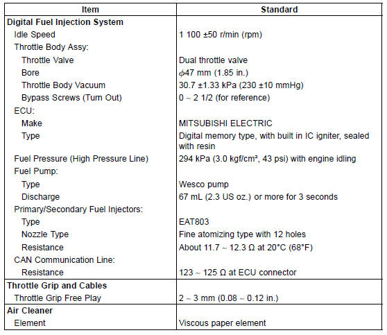
Specifications
 Terminal Numbers of ECU Connectors
 Special Tools and Sealant
Brake Hose and Pipe Damage and Installation Condition Inspection
Inspect the brake hoses, pipes and fittings for deterioration,
cracks and signs of leakage.
The high pressure inside the brake line can cause fluid to
leak [A] or the hose to burst if the line is not properly maintained.
Bend and twist the rubber hose while examining
it.
Replace the ...
Exploded View
25. “1T” marked side faces up.
26. “T2” marked side faces up.
27. Hollow mark faces exhaust side.
G: Apply grease.
L: Apply a non-permanent locking agent.
LG: Apply liquid gasket.
M: Apply molybdenum disulfide grease.
MO: Apply molybdenum disulfide oil solution.
...
Camshaft Chain Tensioner Removal
NOTICE
This is a non-return type camshaft chain tensioner.
The push rod does not return to its original position
once it moves out to take up camshaft chain slack.
Observe all the rules listed below.
When removing the tensioner, do not take out the
mounting bolts only halfway. Retighteni ...