
If this service code appears, check that the following parts are correctly.
Crankshaft Sensor Gear Position Switch Starter Lockout Switch Main Throttle Sensor Rear Wheel Rotation Sensor
If these parts are normal, check the ESD ECU for its ground and power supply (see ESD ECU Power Supply Inspection).
ESD ECU Removal
ESD ECU Installation
Refer to the ESD (Electronic Steering Damper) ECU Installation in the Steering chapter.
ESD ECU Power Supply Inspection
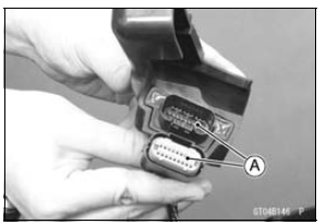
If the connector is clogged with mud or dust, blow it off with compressed air.
If the terminals of the main harness connector are damaged, replace the main harness.
If the terminals of the ESD ECU connectors are damaged, replace the ESD ECU.
Special Tool - Hand Tester: 57001-1394
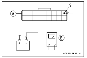
ESD ECU Grounding Inspection Connections: (I) BK/Y lead (ESD ECU terminal 9) ←→ Battery (тАУ) Terminal (II) Engine Ground ←→ Battery (тАУ) Terminal Criteria: Both: 0 Ω
If no continuity, check the connector, the engine ground lead, or main harness, and repair or replace them if necessary.
If the wiring is good, check the power source voltage of the ESD ECU.
NOTE
Be sure the battery is fully charged.
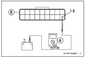
Special Tool - Needle Adapter Set: 57001-1457
ESD ECU Power Supply Inspection Connections:
(I) Digital Meter (+) → Terminal 18 (BR/BK) Digital Meter (тАУ) → Battery (тАУ) terminal
Ignition Switch OFF: 0 V
Ignition Switch ON: Battery Voltage
If the reading is out of the specification, check the following.
Main Fuse 30 A (see Fuse Inspection in the Electrical System chapter) Electronic Steering Damper Fuse 10 A (see Fuse Inspection in the Electrical System chapter) Power Source Wiring (see wiring diagram in this section)
If the fuse and wiring are good, replace the ESD ECU (see ESD (Electronic Steering Damper) ECU Removal/Installation in the Steering chapter).
ESD ECU Power Source Circuit
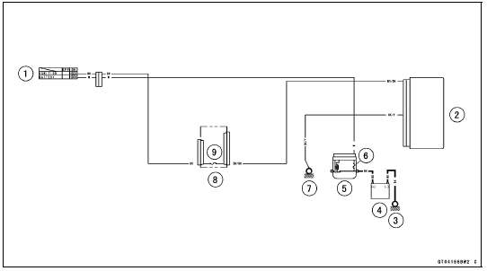
1. Ignition Switch
2. ESD ECU
3. Engine Ground
4. Battery
5. Starter Relay
6. Main Fuse 30 A
7. Frame Ground 3
8. Fuse Box 1
9. ESD Fuse 10 A
 ESD Actuator Input Voltage Inspection
Swingarm Removal
Remove:
Rear Wheel (see Rear Wheel Removal in the
Wheels/Tires chapter)
Mud Guard with Rear Brake Hose (see Mud Guard Removal
in the Frame chapter)
Rocker Arm (see Rocker Arm Removal)
Remove:
Brake Hose Clamp Bolt [A]
Unscrew the swingarm pivot shaft nut [A].
Usi ...
Technical Information-Power Mode
The rider can choose from three engine power modes to suit their preferences
and road conditions.
The FI ECU controls the engine power by adjusting fuel injection, air intake,
and ignition timing. It
enables three-mode selection: Full Power (Mode F), Middle Power (Mode M), and
Low Power (M ...
Stopping the engine
Close the throttle completely.
Shift the transmission into neutral
Turn the ignition key to тАЬOFFтАЭ.
Support the motorcycle on a firm,
level surface with the side stand.
Lock the steering.
NOTE
The motorcycle is equipped with a
vehicle-down sensor, which causes
the engine to sto ...
