
Collars Coupling (Out of rear hub) Grease Seals
NOTICE
Do not lay the wheel on the ground with the disc facing down. This can damage or warp the disc.
Place blocks under the wheel so that the disc does not touch the ground.
Special Tools - Bearing Remover Head, 25 × 28 [B]: 57001-1346
Bearing Remover Shaft, 13 [C]: 57001 -1377
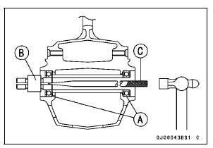
 Hub Bearing
 Hub Bearing Installation
Sidestand Switch Operation Inspection
Raise the rear wheel off the ground with the stand (see
Rear Wheel Removal in the Wheels/Tires chapter).
Inspect the sidestand switch [A] operation accordance to
below table.
Sidestand Switch Operation
If the sidestand switch operation does not work, inspect
or replace the foll ...
Rear Sprocket Warp Inspection
Raise the rear wheel off the ground with the stand so that
it will turn freely.
Set a dial gauge [A] against the rear sprocket [B] near the
teeth as shown in the figure, and rotate [C] the rear wheel
to measure the sprocket runout (warp). The difference
between the highest and lowest di ...
Air Cleaner Housing Installation
For ZX1000JD/KD, be sure to install the pad [A].
Install the clamp bolt heads [A] inside as shown in the
figure.
Install the air cleaner housing on the throttle body assy.
Push in the ducts [B] touch the stoppers [C] of the throttle
body.
Be sure the hoses are routed correctly ...