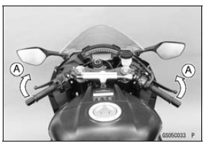

If handlebar movement changes the idle speed, the throttle cables may be improperly adjusted or incorrectly routed, or damaged. Be sure to correct any of these conditions before riding (see Throttle Control System Inspection and Cable, Wire, and Hose Routing section in the Appendix chapter).

| WARNING Operation with improperly adjusted, incorrectly routed or damaged cables could result in an unsafe riding condition. Follow the service manual to be make sure to correct any of these conditions. |
If the idle speed is out of specified range, check the idle speed control valve (see Idle Speed Control Valve Inspection in the Self-Diagnosis System chapter).
Idle Speed Standard: 1 100 В±50 r/min (rpm)
Idle Speed Adjustment
NOTE
This motorcycle is equipped with the idle speed control valve. The idle speed is adjusted automatically at the specified value (1 100 r/min (rpm)) by the idle speed control valve system. Therefore, it is not necessary to adjust the idle speed normally.
 Engine Vacuum Synchronization Inspection
 Fuel Hose Inspection (fuel leak, damage, installation condition)
Fuel Pump Operating Voltage Inspection
NOTE
Be sure the battery is fully charged.
Turn the ignition switch to OFF.
Remove:
Fuel Tank Bolts (see Fuel Tank Removal)
Fuel Tank Bracket Bolts (see Fuel Tank Removal)
Disconnect the fuel pump lead connector and connect the
harness adapter [A] between these connectors as shown
i ...
Nozzle Assy Installation
Replace the dust seals [A] with new ones.
Apply engine oil to the new dust seals, and install them.
Install the nozzle assy securely.
Push the four mounting positions of the injectors.
Set the joint pipe parallel to the air cleaner housing [B].
NOTICE
When installing the nozzle assy, ap ...
Crankcase Assembly
NOTICE
The upper and lower crankcase halves are machined
at the factory in the assembled state, so the
crankcase halves must be replaced as a set.
With a high flash-point solvent, clean off the mating surfaces
of the crankcase halves and wipe dry
WARNINGGasoline and low flash-poin ...