
Replace the fuel hose if any fraying, cracks [B] or bulges [C] are noticed.
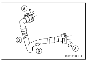
Replace the hose if it has been sharply bent or kinked.
Push and pull [A] the fuel hose joint [B] back and forth more than two times, and make sure it is locked.
Check the other hose joint in the same way.
NOTICE
When pushing and pulling the fuel hose joint, do not apply strong force to the delivery pipe [C] on the nozzle assy. The pipe made from resin could be damaged.
| WARNING Leaking fuel can cause a fire or explosion resulting in serious burns. Make sure the hose joint is installed correctly on the delivery pipe by sliding the joint. |
If it does not locked, reinstall the hose joint.
 Idle Speed Inspection
 Evaporative Emission Control System Inspection (CAL and SEA-B1 Models)
Nozzle Assy Installation
Replace the dust seals [A] with new ones.
Apply engine oil to the new dust seals, and install them.
Install the nozzle assy securely.
Push the four mounting positions of the injectors.
Set the joint pipe parallel to the air cleaner housing [B].
NOTICE
When installing the nozzle assy, ap ...
For Secondary Fuel Injectors
Remove the fuel tank (see Fuel Tank Removal).
Disconnect the injector connector and connect the harness
adapter [A] between these connectors as shown in
the figure.
Main Harness [B]
Secondary Fuel Injector #1 [C]
Special Tool - Measuring Adapter: 57001-1700
Connect a digital me ...
Headlight Bulb Replacement
Turn the cover [A] counterclockwise, and remove it.
Disconnect the headlight connector [A].
Open the clamp [B], and remove the bulb.
NOTICE
When handling the quartz-halogen bulb, never
touch the glass portion with bare hands. Always
use a clean cloth. Oil contamination from hand ...