
NOTE
Be sure the battery is fully charged.
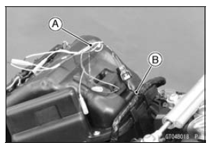
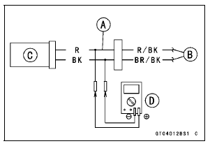
Main Harness [B] Intake Air Temperature Sensor [C]
Special Tool - Measuring Adapter: 57001-1700


Intake Air Temperature Sensor Output Voltage Connections to Adapter: Digital Meter (+) → R (sensor R/BK) lead Digital Meter (–) → BK (sensor BR/BK) lead
Output Voltage Standard: About DC 2.44 ∼ 2.69 V at 25°C (77°F)
NOTE
The output voltage changes according to the intake air temperature.
If the reading is within the standard, check the ECU for its ground, and power supply (see ECU Power Supply Inspection in the Fuel System (DFI) chapter).
If the ground and power supply are good, replace the ECU (see ECU Removal/Installation in the Fuel System (DFI) chapter).
If the reading is out of the standard, remove the ECU and check the wiring for continuity between main harness connectors.
Special Tool - Hand Tester: 57001-1394

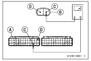
Disconnect the ECU and sensor connectors.
Wiring Inspection ECU Connector [A] ←→ Intake Air Temperature Sensor Connector [B] R/BK lead (ECU terminal 37) [C] BR/BK lead (ECU terminal 13) [D]
If the wiring is good, check the intake air temperature sensor resistance (see Intake Air Temperature Sensor Resistance Inspection).
 Intake Air Temperature Sensor Installation
 Intake Air Temperature Sensor Resistance Inspection
Vehicle-down Sensor Installation
Be sure to install the rubber dampers [A] and collars [B]
on the bracket.
The UP mark [A] of the sensor should face upward.
WARNINGIncorrect installation of the vehicle-down
sensor
could cause sudden loss of engine power. The
rider could lose balance during certain ...
Stick Coil Installation
Apply a thin coat of grease [A] to the stick coils for easy
installation.
Insert the stick coils so that the coil heads align with the
lines [B] on the cylinder head cover.
NOTICE
Do not tap the coil head while installing the coil.
After installation, be sure the stick coils are ...
Spring Preload Adjustment
The spring preload adjuster is located
at the lower end of each front fork leg
and can be adjusted.
To increase spring preload and
stiffen the suspension, turn the
preload adjuster clockwise with a
hexagon wrench.
To decrease preload and soften the
suspension, turn the preload adjust ...