
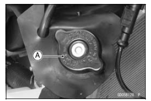
Remove the radiator cap in two steps. First turn the cap counterclockwise to the first stop. Then push and turn it further in the same direction and remove the cap.
NOTE
Wet the cap sealing surfaces with water or coolant to prevent pressure leaks.
NOTICE
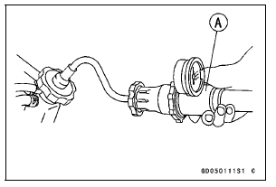
During pressure testing, do not exceed the pressure for which the system is designed. The maximum pressure is 142 kPa (1.45 kgf/cm², 21 psi).
If the pressure holds steady, the system is all right.
If the pressure drops and no external source is found, check for internal leaks. Droplets in the engine oil indicate internal leakage. Check the cylinder head gasket and the water pump.
Remove the pressure tester, replenish the coolant, and install the radiator cap.
 Coolant Deterioration Inspection
 Cooling System Flushing
Exploded View
EO: Apply engine oil.
G: Apply grease.
L: Apply a non-permanent locking agent.
Lh: Left-hand Threads
MO: Apply molybdenum disulfide oil solution.
(mixture of the engine oil and molybdenum disulfide grease in a weight ratio
10:1)
R: Replacement Parts
S: Follow the specified t ...
Air Suction System Damage Inspection
Separate the air switching valve hose [A] from the lower
air cleaner housing [B] (see Air Cleaner Housing Removal
in the Fuel System (DFI) chapter).
Connect the following parts temporarily.
Fuel Pump Lead Connector [A]
Extension Tube [B]
Air Cleaner Housing (see Air Cleaner Hou ...
Steering Damper Installation
Install the following parts as shown in the figure.
Collar [A]
Washer (t = 3.5 mm, 0.14 in.) [B]
Steering Damper [C] (
ZX1000JC/KC)
Electronic Steering Damper [D] (ZX1000JD/KD)
Washer (t = 1.2 mm, 0.05 in.) [E]
Apply a non-permanent locking agent to the threads of
the steering ...