
The self-diagnosis system is monitoring the following mechanisms.
DFI System and Ignition System
S-KTRC System
Immobilizer System (Equipped Models)
KIBS and ABS (Equipped Models)
ESD (Electronic Steering Damper) System
(ZX1000JD/KD)
The following warning indicator lights (LED) are used for
symbols of below table.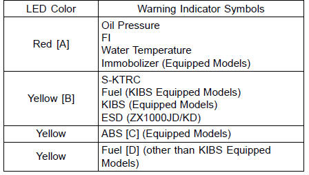
The self-diagnosis system has two modes and can be switched to another mode by operating the meter unit.
User Mode
The ECU notifies the rider of troubles in DFI system, ignition system, S-KTRC system and immobilizer system (equipped models) by lighting or blinking the warning indicator light (LED) [A], FI warning symbol [B] and immobilizer warning symbol [C] when DFI, ignition, S-KTRC and immobilizer system parts are faulty, and initiates fail-safe function. In case of serious troubles, ECU stops the injection and ignition operations.
For KIBS and ABS system (equipped models), the KIBS hydraulic unit notifies the rider of troubles in KIBS and ABS system by lighting or blinking the red warning indicator light (LED) [A], KIBS warning symbol [B] and ABS indicator light (LED) [C] when KIBS and ABS parts are faulty, and initiates fail-safe function.
For ESD system (ZX1000JD/KD), the ESD ECU notifies the rider of troubles in ESD system by lighting the yellow warning indicator light (LED) and ESD warning symbol [D] when ESD parts are faulty, and initiates fail-safe function.
Dealer Mode
The LCD (Liquid Crystal Display) displays the service code(s) [A] to show the problem(s) which the above system has at the moment of diagnosis.
 Self-Diagnosis
 Self-Diagnosis Procedures
Brake Fluid Leak (Brake Hose and Pipe) Inspection
For KIBS equipped models, remove the fuel tank (see
Fuel Tank Removal in the Fuel System (DFI) chapter).
Apply the brake lever or pedal and inspect the brake fluid
leak from the brake hoses [A], pipes (KIBS equipped models)
[B] and fittings [C].
If the brake fluid leaked from any posit ...
Cable, Wire, and Hose Routing
1. Clamp (Hold the regulator/rectifier lead. Run the lead inside of the
installation hole.)
2. Clamp (Bend down the clamp, and hold the main harness and the vacuum hose
(equipped
models).)
3. Clamp (Hold the air intake solenoid valve lead (equipped models).)
4. Run the vacuum hose under ...
Piston Ring, Piston Ring Groove Wear Inspection
Check for uneven groove wear by inspecting the ring seating.
The rings should fit perfectly parallel to groove surfaces.
If not, replace the piston and all the piston rings.
With the piston rings in their grooves, make several measurements
with a thickness gauge [A] to determine pisto ...