
DFI Diagnosis Flow Chart
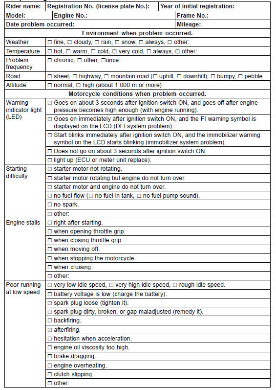
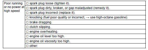
Sample Diagnosis Sheet
 Outline
 DFI System Troubleshooting Guide
Coupling Bearing Removal
Remove:
Coupling
Grease Seal
Circlip [A]
Special Tool - Inside Circlip Pliers: 57001-143
Remove the bearing [A] by tapping from the wheel side.
Special Tool - Bearing Driver Set [B]: 57001-1129
...
Exhaust Pipe Installation
Replace the exhaust pipe gaskets [A] and premuffler
chamber gasket [B] with new ones.
Install the premuffler chamber gasket to the premuffler
chamber [C] until it is bottomed so that the chamfer side
faces exhaust pipe [D].
Install the exhaust pipe clamp [E] as shown in the figure.
I ...
Transmission Shaft Disassembly
Remove the transmission shafts (see Transmission Shaft
Removal).
Remove the circlips, and then disassemble the transmission
shafts.
Special Tool - Outside Circlip Pliers: 57001-144
The 5th gear [A] on the output shaft has three steel balls
assembled into it for the positive neutral fin ...