
Sidestand Switch Operation
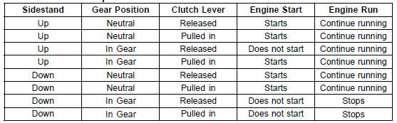
If the sidestand switch operation does not work, inspect or replace the following parts.
Battery (see Charging Condition Inspection in the Electrical System chapter)
Main Fuse 30 A (see Fuse Inspection in the Electrical System chapter) Ignition Fuse 15 A (see Fuse Inspection in the Electrical System chapter) Ignition Switch (see Switch Inspection in the Electrical System chapter) Sidestand Switch (see Switch Inspection in the Electrical System chapter) Engine Stop Switch (see Switch Inspection in the Electrical System chapter) Starter Button (see Switch Inspection in the Electrical System chapter) Gear Position Switch (see Gear Position Switch Inspection in the Electrical System chapter) Starter Lockout Switch (see Switch Inspection in the Electrical System chapter) Starter Relay (see Starter Relay Inspection in the Electrical System chapter) Relay Box (see Relay Circuit Inspection in the Electrical System chapter) Starter Circuit Relay (see Relay Circuit Inspection in the Electrical System chapter) Harness (see Wiring Inspection in the Electrical System chapter)
If the all parts are good condition, replace the ECU (see ECU Removal/Installation in the Fuel System (DFI) chapter).
 Headlight Aiming Adjustment
 Engine Stop Switch Operation Inspection
Air Intake Duct Removal
Remove:
Upper Fairing Assembly (see Upper Fairing Assembly
Removal in the Frame chapter)
Meter Bracket (see Meter Unit Removal/Installation in
the Electrical System chapter)
Immobilizer Amplifier [A] (Equipped Models) (see Immobilizer
System Parts Replacement in the Electrical System
...
Subthrottle Sensor Input Voltage Inspection
NOTE
Be sure the battery is fully charged.
Turn the ignition switch to OFF.
Remove the air cleaner housing (see Air Cleaner Housing
Removal in the Fuel System (DFI) chapter)
Disconnect the subthrottle sensor connector and connect
the harness adapter [A] between these connectors.
Spec ...
Storage of Removed Parts
After all the parts including subassembly parts have been
cleaned, store the parts in a clean area. Put a clean cloth
or plastic sheet over the parts to protect from any foreign
materials that may collect before re-assembly.
Inspection
Reuse of worn or damaged parts may lead to serious acci ...