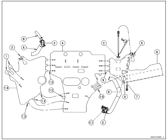


1. Hold the water hose [A]. Insert the tab into the slot.
2. Hold the water hose [B]. Insert the tab into the slot.
3. Water Hose Fitting on Cylinder Head
4. Heat Insulation Rubber Plate
5. Run the crankshaft sensor lead and the oil pressure switch lead into the slot, and hook the slot on the grommet of the crankshaft sensor [C].
6. Right Heat Insulation Rubber Plate
7. Run the crankshaft sensor lead to inside of the rubber plate.
8. Run the water hose [D], and hook the water hose clamp screw [E].
9. Insert the tabs into the slots.
10. Place this portion to inside of the right heat insulation rubber plate.
11. Thermostat
12. Run the gear position switch lead here.
13. Insert the tabs into the slots.
14. Left Heat Insulation Rubber Plate
 Engine No. ZXT00JE003023
 Troubleshooting Guide
Shift Fork/Gear Groove Wear Inspection
Measure the thickness of the shift fork ears [A], and measure
the width [B] of the gear grooves.
If the thickness of a shift fork ear is less than the service
limit, the shift fork must be replaced.
Shift Fork Ear Thickness
Standard: 5.7 6.0 mm (0.224
0.236 in.)
Service Limit: 5.6 mm ...
Torque Limiter Installation
Apply molybdenum disulfide grease to the torque limiter
shaft [A].
Install the torque limiter [B], the collar [C] and the shaft.
Turn the large-hole end of the shaft to inside as shown in
the figure.
Replace the washer [D] with a new one.
Apply a non-permanent locking agent to the t ...
Air Switching Valve Removal
NOTICE
Never drop the air switching valve especially on a
hard surface. Such a shock to the air switching
valve can damaged it.
Remove the air cleaner housing (see Air Cleaner Housing
Removal in the Fuel System (DFI) chapter).
Disconnect the connector [A].
Disconnect the hoses [B] from ...