
Main Throttle Sensor [A] Subthrottle Sensor [B] Idle Speed Control Valve Actuator [C] Subthrottle Valve Actuator [D] Intake Air Pressure Sensor #2 [E] Stick Coils #1, #2, #3, #4 [F] Air Switching Valve [G] Intake Air Pressure Sensor #1 [H]
Water Temperature Sensor [A] Primary Fuel Injectors #1, #2, #3, #4 [B]
Battery [A] Exhaust Butterfly Valve Actuator [B] ECU Fuse 15 A [C] Immobilizer (Equipped Models)/Kawasaki Diagnostic System Connector [D] Vehicle-down Sensor [E]
ECU [A] Relay Box [B] (Fuel Pump Relay, Radiator Fan Relay)
Fuel Pump [A]
Secondary Fuel Injectors #1, #2, #3, #4 [A] Intake Air Temperature Sensor [B]
Crankshaft Sensor [A]
Gear Position Switch [A]
Ignition Key [A] (Transponder, Immobilizer System Equipped Models) Immobilizer Antenna [B] (Equipped Models) Ignition Switch [C] Warning Indicator Light (LED) [D]
Immobilizer Amplifier [A] (Equipped Models) Air Intake Solenoid Valve [B] (Other than US, CA and CAL Models)
Oxygen Sensor [A] (Equipped Models)
Front Wheel Rotation Sensor [A]
Rear Wheel Rotation Sensor [A]
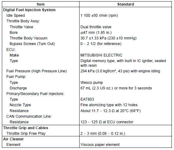
Specifications
 Terminal Numbers of ECU Connectors
 Special Tools and Sealant
External Shift Mechanism Installation
Install the gear positioning lever [A] as shown in the figure.
Install:
Spring [B]
Washer [C]
Tighten:
Torque - Gear Positioning Lever Bolt [D]: 12 N·m (1.2 kgf·m,
106 in·lb)
Assemble:
Ratchet [A]
Pawls [B]
Pins [C]
Springs [D]
Install the shift ratchet ...
Relay Box Removal
Remove the left fuel tank cover (see Fuel Tank Removal
in the Fuel System (DFI) chapter).
Disconnect the connectors [A].
Pull out the relay box [B] from the rubber protector [C].
NOTE
The relay box has relays and diodes. The relays and
diodes can not be removed.
Relay Box Installa ...
Check 3-1: CAN Communication Line Resistance Inspection
Set the hand tester [A] to the ×1 Ω range and connect it
to the terminal [11] and [12] in the meter unit.
Special Tool - Hand Tester: 57001-1394
CAN Communication Line Resistance (at Meter Unit)
Standard: 122 126 Ω
If the tester reading is not specified, replace the meter ...