
NOTE
Do not turn the bolts [A] because the reflector in the headlight comes off.
(In the photo, the headlight unit has been removed for clarity.)
NOTE
The left adjuster [A] and right adjuster [B] can move the
direction of the headlight beam to up, down, left and
right by turning each adjuster itself as the below table.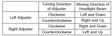
NOTE
On high beam, the brightest points should be slightly below horizontal with the motorcycle on its wheels and the rider seated. Adjust the headlight to the proper angle according to local regulations.
NOTE
For US model, the proper angle is 0.4° below horizontal.
This is 50 mm (2 in.) drop at 7.6 m (25 ft) measured from the center of the headlight with the motorcycle on its wheels and the rider seated.
50 mm (2 in.) [A] Center of Brightest Spot [B] 7.6 m (25 ft) [C] Height of Headlight Center [D]
 Lights and Switches Operation Inspection
 Sidestand Switch Operation Inspection
Fuel Hose Replacement
Remove the fuel tank (see Fuel Tank Removal in the Fuel
System (DFI) chapter).
WARNINGFuel is flammable and explosive under
certain conditions
and can cause severe burns. Be prepared
for fuel spillage; any spilled fuel must be completely
wiped up immediately. When the fue ...
Rear Caliper Removal
Remove:
Bolt [A]
Rear Wheel Rotation Sensor [B]
Loosen the banjo bolt [C] at the brake hose lower end,
and tighten it loosely.
Loosen the caliper holder pin [D].
Remove the rear wheel (see Rear Wheel Removal in the
Wheels/Tires chapter).
Unscrew the banjo bolt and remove t ...
Oxygen Sensor Removal (Equipped Models)
Remove:
Fuel Tank (see Fuel Tank Removal in the Fuel System
(DFI) chapter)
Right Lower Fairing (see Lower Fairing Removal in the
Frame chapter)
Disconnect the oxygen sensor lead connector [A].
NOTICE
Do not pull strongly, twist, or bend the oxygen sensor
lead. This may cause the wi ...