
Sidestand Switch Operation
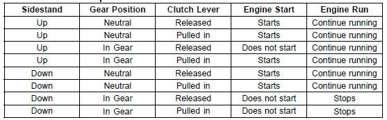
If the sidestand switch operation does not work, inspect or replace the following parts.
Battery (see Charging Condition Inspection in the Electrical System chapter)
Main Fuse 30 A (see Fuse Inspection in the Electrical System chapter) Ignition Fuse 15 A (see Fuse Inspection in the Electrical System chapter) Ignition Switch (see Switch Inspection in the Electrical System chapter) Sidestand Switch (see Switch Inspection in the Electrical System chapter) Engine Stop Switch (see Switch Inspection in the Electrical System chapter) Starter Button (see Switch Inspection in the Electrical System chapter) Gear Position Switch (see Gear Position Switch Inspection in the Electrical System chapter) Starter Lockout Switch (see Switch Inspection in the Electrical System chapter) Starter Relay (see Starter Relay Inspection in the Electrical System chapter) Relay Box (see Relay Circuit Inspection in the Electrical System chapter) Starter Circuit Relay (see Relay Circuit Inspection in the Electrical System chapter) Harness (see Wiring Inspection in the Electrical System chapter)
If the all parts are good condition, replace the ECU (see ECU Removal/Installation in the Fuel System (DFI) chapter).
 Headlight Aiming Adjustment
 Engine Stop Switch Operation Inspection
Tire Tread Wear Inspection
As the tire tread wears down, the tire becomes more susceptible
to puncture and failure. An accepted estimate is
that 90% of all tire failures occur during the last 10% of tread
life (90% worn). So it is false economy and unsafe to use
the tires until they are bald.
Measure the tread depth a ...
Self-Diagnosis Procedures
NOTE
Use a fully charged battery when conducting
self-diagnosis. Otherwise, the light (LED) and symbol
do not light or blink.
Turn the ignition switch to ON.
When a problem occurs with DFI system and ignition system,
the warning indicator light (LED) [A] goes on and
FI warning symbol ...
Air Switching Valve Installation
Install the air switching valve [A] with hose [B] as shown
in the figure.
Front [C]
Left Side View [D]
White Paint [E]
Air Switching Valve Operation Test
Refer to the Air Suction System Damage Inspection in the
Periodic Maintenance chapter.
Air Switching Valve Unit Test ...