
NOTE
Valve clearance must be checked and adjusted when the engine is cold (at room temperature).
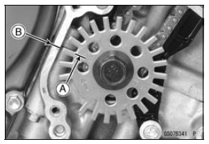
TDC Mark [A] for #1, 4 Pistons Timing Mark [B] (Crankcase Halves Mating Surface)

Valve Clearance
Standard:
Exhaust 0.17  0.22 mm (0.0067
 0.0087 in.)
Intake 0.15  0.22 mm (0.0059
 0.0087 in.)

NOTE
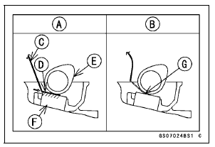
Thickness gauge is horizontally inserted on the valve lifter.
Appropriateness [A] Inadequacy [B] Thickness Gauge [C] Horizontally Inserts [D] Cam [E] Valve Lifter [F] Hits the Valve Lifter Ahead [G]

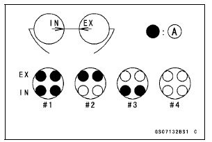
When positioning #1 piston TDC at the end of the compression stroke:
Intake Valve Clearance of #1 and #3 Cylinders Exhaust Valve Clearance of #1 and #2 Cylinders Measuring Valve [A]

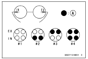
When positioning #4 piston TDC at the end of the compression stroke:
Intake Valve Clearance of #2 and #4 Cylinders Exhaust Valve Clearance of #3 and #4 Cylinders Measuring Valve [A]

If the valve clearance is not within the specified range, first record the clearance, and then adjust it.
 Engine Top End
 Valve Clearance Adjustment
Meter instruments
Upper Button
Lower Button
Tachometer (with Shift-Up
Indicator)
Red Zone
Ambient Brightness
Sensor
Turn Signal Indicator Light
Warning Indicator Light
(Red)
Neutral Indicator Light
Multifunction Meter
High Beam Indicator Light
Warning Indicator Light
(Yellow)
Fuel ...
Intake Air Pressure Sensor #2 Output Voltage Inspection
Measure the output voltage at the intake air pressure sensor
#2 in the same way as input voltage inspection, note
the following.
Disconnect the intake air pressure sensor #2 connector
and connect the measuring adapter [A] between these
connectors.
[B] Main Harness
[C] Intake Air Pressu ...
Meter Unit Inspection
Remove the meter unit (see Meter Unit Removal).
[1] Battery (+)
[2] Fuel Reserve Switch
[3] Ground (–)
[4] Unused
[5] Right Turn Signal Indicator Light (LED) (+)
[6] Left Turn Signal Indicator Light (LED) (+)
[7] High Beam Indicator Light (LED) (+)
[8] Neutral Indicator Light (LED) (в ...