
NOTE
Mark and record the locations of the valve lifters and shims so that they can be reinstalled in their original positions.
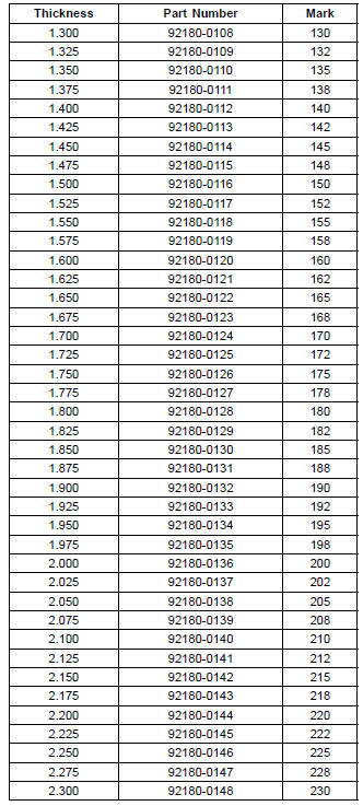
a + b – c = d
[a] Present Shim Thickness
[b] Measured Valve Clearance
[c] Specified Valve Clearance (Mean Value = 0.195 mm (Exhaust), 0.185 mm (Intake))
[d] Replace Shim Thickness
Example (Exhaust): 1.600 + 0.28 – 0.195 = 1.685 mm
Exchange the shim for the 1.675 size shim.
Adjustment Shims
NOTICE
Be sure to remeasure the clearance after selecting a shim. The clearance can be out of the specified range because of the shim tolerance.
If there is no valve clearance, use a shim that is a few sizes smaller, and remeasure the valve clearance.
NOTICE
Do not put shim stock under the shim. This may cause the shim to pop out at high rpm, causing extensive engine damage.
Do not grind the shim. Thismay cause it to fracture, causing extensive engine damage.
 Valve Clearance Inspection
 Air Suction System Damage Inspection
Wheels
Tubeless tires are installed on the
wheels of this motorcycle. The indications
of “TUBELESS” on the tire side
wall and the rim show that the tire and
rim are specially designed for tubeless
use.
A. “TUBELESS” Mark
A. “TUBELESS” Mark
The tire and rim form a leakproof unit
by ...
Warning Indicator Light (Red)
This red warning indicator light and
the oil pressure warning symbol ( )
should go on whenever the ignition
switch is turned to “ON” and go off after
starting the engine.
A. Warning Indicator Light (Red)
B. Warning Symbols
This red warning indicator light has
the two warning function ...
Oil Filter Replacement
Drain the engine oil (see Engine Oil Change).
Remove the left lower fairing (see Lower Fairing Removal
in the Frame chapter).
Remove the oil filter [A] with the oil filter wrench [B].
Special Tool - Oil Filter Wrench: 57001-1249
Replace the filter with a new one.
Apply grease t ...