
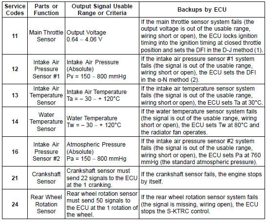
Note:
(1): D-J Method: When the engine load is light like at idling or low speed, the ECU determines the injection quantity by calculating from the throttle vacuum (vacuum sensor output voltage) and engine speed (crankshaft sensor output voltage). This method is called D-J method.
(2): α-N Method: As the engine speed increases, and the engine load turns middle to heavy, the ECU determines the injection quantity by calculating from the throttle opening (throttle sensor output voltage) and the engine speed. This method is called α-N method.
*: This depends on the number of stopped cylinders.
The main throttle sensor is a rotating variable resistor that change output voltage according to throttle operating. The ECU senses this voltage change and determines fuel injection quantity, and ignition timing according to engine rpm, and throttle opening.
Input Terminal [A]: BL Output Terminal [B]: V/W Ground Terminal [C]: BR/BK
 Service Code Erasing
Rear Wheel Removal
Raise the rear wheel off the ground with the stand [A].
Remove:
Cotter Pin [A]
Rear Axle Nut [B]
Washer [C]
Rear Axle [D] (from Right Side)
Remove the rear wheel rotation sensor from the caliper
bracket (see Rear Wheel Rotation Sensor Removal in the
Brakes chapter).
...
Clutch Cover Removal
Remove:
Right Lower Fairing (see Lower Fairing Removal in the
Frame chapter)
Clutch Cable Lower End (see Cable Removal)
Clutch Cover Bolts [A]
Turn the release lever [A] counterclockwise as shown,
and remove the clutch cover.
About 90° [B]
...
Cylinder Head Cover Removal
Remove:
Air Suction Valves (see Air Suction Valve Removal)
Throttle Body Assy (see Throttle Body Assy Removal in
the Fuel System (DFI) chapter)
Stick Coils (see Stick Coil Removal in the Electrical System
chapter)
Remove the clamps [A].
Turn up the front side of the heat insulation ...
