
Main Throttle Sensor [A] Subthrottle Sensor [B] Idle Speed Control Valve Actuator [C] Subthrottle Valve Actuator [D] Intake Air Pressure Sensor #2 [E] Stick Coils #1, #2, #3, #4 [F] Air Switching Valve [G] Intake Air Pressure Sensor #1 [H]
Water Temperature Sensor [A] Primary Fuel Injectors #1, #2, #3, #4 [B]
Battery [A] Exhaust Butterfly Valve Actuator [B] ECU Fuse 15 A [C] Immobilizer (Equipped Models)/Kawasaki Diagnostic System Connector [D] Vehicle-down Sensor [E]
ECU [A] Relay Box [B] (Fuel Pump Relay, Radiator Fan Relay)
Fuel Pump [A]
Secondary Fuel Injectors #1, #2, #3, #4 [A] Intake Air Temperature Sensor [B]
Crankshaft Sensor [A]
Gear Position Switch [A]
Ignition Key [A] (Transponder, Immobilizer System Equipped Models) Immobilizer Antenna [B] (Equipped Models) Ignition Switch [C] Warning Indicator Light (LED) [D]
Immobilizer Amplifier [A] (Equipped Models) Air Intake Solenoid Valve [B] (Other than US, CA and CAL Models)
Oxygen Sensor [A] (Equipped Models)
Front Wheel Rotation Sensor [A]
Rear Wheel Rotation Sensor [A]
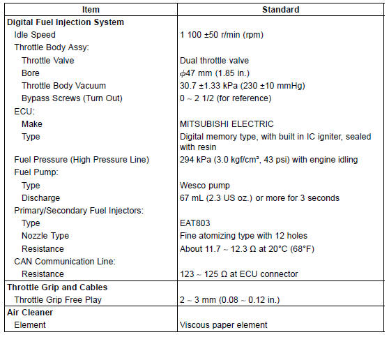
Specifications
 Terminal Numbers of ECU Connectors
 Special Tools and Sealant
ECU Power Supply Inspection
Remove the upper air cleaner housing (see Air Cleaner
Element Replacement in the Periodic Maintenance chapter).
Visually inspect the ECU connectors.
If the connector is clogged with mud or dust, blow it off
with compressed air.
Remove the ECU (see ECU Removal).
Visually inspect the ...
Piston Removal
Remove:
Crankshaft (see Crankshaft Removal)
Remove the piston together with the connecting rod to the
cylinder head side.
NOTICE
Discard the connecting rod bolts and nuts. To prevent
damage to the crankpin surfaces, do not allow
the connecting rod bolts to bump against the
crankpins. ...
Rear Shock Absorber Installation
Replace the rear shock absorber nuts and tie-rod nuts
with new ones.
Tighten:
Torque - Rear Shock Absorber Nuts: 34 N·m (3.5 kgf·m, 25
ft·lb)
Tie-Rod Nuts: 34 N·m (3.5 kgf·m, 25 ft·lb)
When installing the rear shock absorber bracket [A], install
it so that the recess side [B] ...