
1. Timing Rotor
2. Crankshaft Sensor
3. Horn
4. Oil Pressure Switch
5. Rear Brake Light Switch
6. Oxygen Sensor (Equipped Models)
7. Alternator
8. Stator Coil
9. Gear Position Switch
10. Sidestand Switch
11. Immobilizer Amplifier (Equipped Models)
12. Radiator Fan Motor
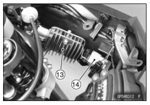
13. Regulator/Rectifier
14. Fuse Box 1
15. Relay Box
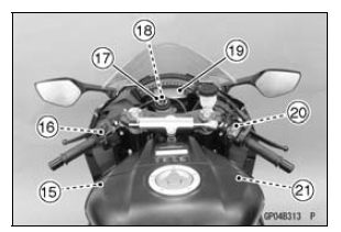
16. Starter Lockout Switch
17. Ignition Switch
18. Immobilizer Antenna (Equipped Models, Included in Ignition Switch)
19. Meter Unit
20. Front Brake Light Switch
21. ECU
22. Air Switching Valve
23. Stick Coils
24. Spark Plugs
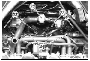
25. Water Temperature Sensor
26. Starter Motor
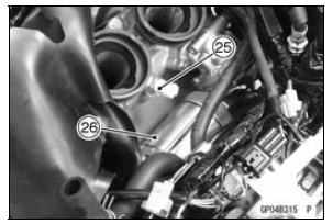
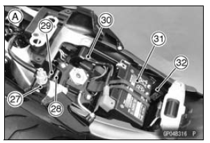
27. Vehicle-down Sensor
28. Fuse Box 2
29. Fuse Box 3 (KIBS Equipped Models)
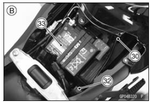
30. Starter Relay
31. Battery 12 V 8.6 Ah
32. Turn Signal Relay
A. ZX1000K Model
33. Battery 12 V 6 Ah
B. ZX1000J Model
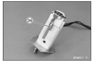
34. Fuel Reserve Switch (Included in Fuel Pump)
This page intentionally left blank.
 Special Tools and Sealant
 Wiring Diagram (US, CA and CAL without KIBS Models)
Shift Fork Guide Pin/Drum Groove Wear Inspection
Measure the diameter of each shift fork guide pin [A], and
measure the width [B] of each shift drum groove.
If the guide pin on any shift fork is less than the service
limit, the fork must be replaced.
Shift Fork Guide Pin Diameter
Standard: 6.9 7.0 mm (0.272
0.276 in.)
Service Limit: ...
Windshield and Other Plastic Parts
After washing use a soft cloth to
gently dry plastic parts. When dry,
treat the windshield, headlight lens,
and other nonpainted plastic parts with
an approved plastic cleaner/polisher
product.
NOTICE
Plastic parts may deteriorate
and break if they come in contact
with chemical substances
...
KIBS Troubleshooting Outline
When an abnormality in the system occurs, the ABS indicator
light (LED) and KIBS indicator light (LED) light up and
the KIBS warning symbol are displayed on the LCD (Liquid
Crystal Display) to alert the rider. In addition, the nature of
the fault is stored in the memory of the KIBS hydraulic uni ...