Kawasaki Ninja Service Manual: Shift Pedal Installation
- Install the rubber damper to the shift pedal.
Turn the chamfered side to inside.
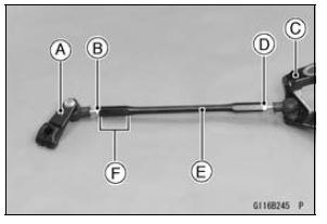
- Assemble:
Shift Lever [A] and Locknut [B] (Left-hand Thread)
Shift Pedal [C] and Locknut [D]
Tie-Rod [E]
Turn the grooved end [F] of the tie-rod to the shift lever.
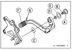
- Apply grease to the sliding surface [A] on the shift pedal
mounting bolt [B].
- Apply a non-permanent locking agent to the thread of the
shift pedal mounting bolt.
- Install:
Washer [C] (Inside Diameter: 8.2 mm, 0.32 in.)
Shift Pedal Assembly
Washer [D] (Frame No. JKAZXCJ1CA011772
 Outside
Diameter: 16 mm, 0.63 in.)
Washer [E] (Frame No. JKAZXCJ1CA011772
 Inside
Diameter: 18.3 mm, 0.72 in.)
- Tighten:
Torque - Shift Pedal Mounting Bolt: 25 N·m (2.5 kgf·m, 18
ft·lb)
- When installing the rubber damper [F], install it so that the
chamfered side [G] faces inward.
- Align the punch mark on the shift shaft with the slit [A] of
the shift lever.
- Tighten the shift lever bolt.
- After installation, the shift pedal lower surface [B] aligns
with the tie-rod lower surface [C].
If the pedal position is different, adjust it as follows.
- To adjust the pedal position, loosen the front locknut (left
-hand threads) and rear locknut, and then turn the tie-rod.
- Tighten the locknuts securely.
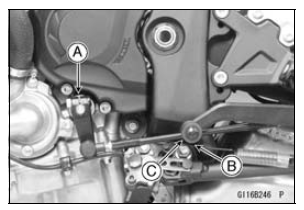
Remove:
Shift Lever Bolt [A]
Front Footpeg Bracket Bolts [B]
If the tie-rod [C] is to be removed from the shift pedal and
the shift lever, loosen the tie-rod locknuts [D].
The front tie-ro ...
Remove:
Shift Lever (see Shift Pedal Removal)
Oil Pump Drive Gear (see Oil Pump Drive Gear Removal/
Installation in the Engine Lubrication System
chapter)
Circlip [A]
Washer [B]
Spec ...
Other materials:
Rebound Damping Force Adjustment
The rebound damping force adjuster
is located at the upper end of the rear
shock absorber.
A. Rebound Damping Force Adjuster
B. To increase damping force
C. To decrease damping force
Using a screwdriver turn the rebound
damping force adjuster clockwise
to increase rebound damping or ...
Starter Motor Assembly
Install the positive brush assy [A] and the starter motor
terminal [B] as shown in the figure.
Replace the O-ring [C] with a new one, and install it.
Install:
Brush Springs [A]
Negative Brush Assy [B]
Turn the stopper side [C] to inside.
Tighten:
Torque - Brush Holder S ...
Nozzle Assy Installation
Replace the dust seals [A] with new ones.
Apply engine oil to the new dust seals, and install them.
Install the nozzle assy securely.
Push the four mounting positions of the injectors.
Set the joint pipe parallel to the air cleaner housing [B].
NOTICE
When installing the nozzle assy, ap ...

 Shift Pedal Removal
 External Shift Mechanism Removal