
NOTE
Be sure the battery is fully charged.
Special Tool - Throttle Sensor Setting Adapter: 57001 -1538
Subthrottle Sensor Input Voltage Connections to Adapter: Digital Meter (+) → W (sensor BL) lead Digital Meter (–) → BK (sensor BR/BK) lead
ECU Intake Air Temperature Sensor
Input Voltage
Standard: DC 4.75  5.25 V
If the reading is within the standard, check the output voltage (see Subthrottle Sensor Output Voltage Inspection).
If the reading is out of the standard, remove the ECU and check the wiring for continuity between harness connectors.
Special Tool - Hand Tester: 57001-1394
Disconnect the ECU and sensor connectors.
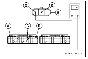
Wiring Continuity Inspection ECU Connector [A] ←→ Subthrottle Sensor Connector [B] BL lead (ECU terminal 9) [C] BR/BK lead (ECU terminal 13) [D]
If the wiring is good, check the ECU for its ground and power supply (see ECU Power Supply Inspection in the Fuel System (DFI) chapter).
If the ground and power supply are good, replace the ECU (see ECU Removal/Installation in the Fuel System (DFI) chapter).
 Subthrottle Sensor Removal/Adjustment
 Subthrottle Sensor Output Voltage Inspection
Exhaust Butterfly Valve Actuator Removal
NOTICE
Never drop the exhaust butterfly valve actuator especially
on a hard surface. Such a shock to the actuator
can damage it.
Remove:
Front Seat (see Front Seat Removal in the Frame chapter)
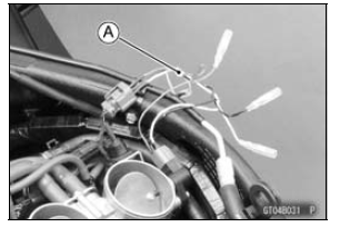
Clamp [A]
Screws [B] and Washers
Slide the covers [A] and loosen the lock nuts [B] ...
Cable, Wire, and Hose Routing
1. Clamp (Hold the regulator/rectifier lead. Run the lead inside of the
installation hole.)
2. Clamp (Bend down the clamp, and hold the main harness and the vacuum hose
(equipped
models).)
3. Clamp (Hold the air intake solenoid valve lead (equipped models).)
4. Run the vacuum hose under ...
Alternator Cover Removal
Remove:
Upper Fairing Assembly (see Upper Fairing Assembly
Removal in the Frame chapter)
Air Cleaner Housing (see Air Cleaner Housing Removal
in the Fuel System (DFI) chapter)
Bolt [A]
Bring the heat insulator plate [B] forward to remove the
alternator lead connector.
Clear the p ...