
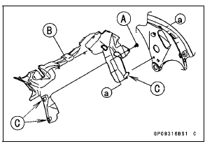
Clear the projections [C] from the main frame.
 Charging System
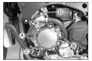
 Alternator Cover Installation
Immobilizer Amplifier Replacement
Remove the upper fairing assembly (see Upper Fairing
Assembly Removal in the Frame chapter).
Disconnect the connector [A].
Pull out the immobilizer amplifier [B] together with the rubber
protector [C] from the air intake duct [D].
ECU Replacement
Refer to the ECU Removal/Instal ...
Tie-Rod and Rocker Arm Bearing Removal
Remove:
Tie-Rod (see Tie-Rod Removal)
Rocker Arms (see Rocker Arm Removal)
Swingarm (see Swingarm Removal)
Sleeves [A]
Oil Seals [B]
Remove the needle bearings [C], using the bearing remover
head and bearing remover shaft.
Special Tools - Bearing Remover Head,
15 ×
17: ...
Water Pump Inspection
Remove the left lower fairing (see Lower Fairing Removal
in the Frame chapter).
Check the drainage outlet passage [A] at the bottom of
the water pump body for coolant leaks.
If the mechanical seal is damaged, the coolant leaks
through the seal and drains through the passage. Replace
th ...