
The rider can choose from three engine power modes to suit their preferences and road conditions.
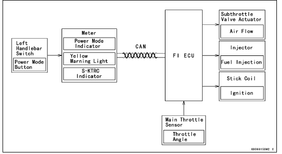
The FI ECU controls the engine power by adjusting fuel injection, air intake, and ignition timing. It enables three-mode selection: Full Power (Mode F), Middle Power (Mode M), and Low Power (Mode L).
In addition, combining each mode with each S-KTRC setting allows the rider to have more choices to be able to interact with various conditions.
Power Mode Operation
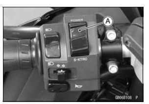
To change the mode, close the throttle grip completely,
and depress the power mode button [A] (0.3
 0.4 sec.).
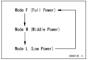
Power Mode Positions
NOTE
The power mode setting is maintained when the ignition switch is turned OFF, or when the battery is disconnected.
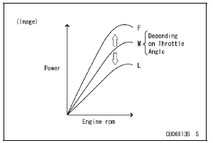
Mode F: The highest engine power output is achieved. The rider can use the full power of the engine.
Mode M: The throttle response is less sharp compared to mode F. Depending on the throttle application, full power can be accessed temporarily.
Mode L: About 60% of the highest engine power output is achieved. The throttle response is mildest among the three modes.
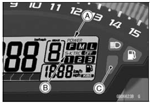
The current mode selection is displayed on the power mode indicator [A] in the multifunction meter.
If a failure occurs with a FI related components such as a subthrottle or main throttle sensor, the warning indicator light (red LED) and FI warning symbol will go ON, and/or the S-KTRC indicator [B] and warning indicator light (yellow LED) [C] blink. The current mode cannot be changed at this time.
 Mode-switching
Front Wheel Rotation Sensor Signal Abnormal (Service Code b 42)
Measure the air gap between the front wheel rotation sensor
and sensor rotor.
Thickness Gauge [A]
Air Gap
Standard: 0.4 1.6 mm (0.02
0.06 in.)
If the measurement is not the standard, check each part
for deformation and looseness and correct accordingly.
If the measurement is t ...
Economical Riding Indicator
When the operator is driving the motorcycle
for optimum fuel-efficiency, the
economical riding indicator appears on
the multifunction meter to indicate favorable
fuel consumption. Monitoring
the economical riding indicator can
help the rider maximize fuel efficiency.
A. Economical Riding ...
Brake Lever Adjuster
There is an adjuster on the brake
lever. The adjuster has 6 positions so
that the released lever position can be
adjusted to suit the operator’s hands.
Push the lever forward and turn the adjuster
to align the number with the mark
on the lever holder. The distance from
the grip to the rel ...
