
Depress the S-KTRC button on the left handlebar switch to change the mode. The mode can be changed only when the throttle grip is closed completely.
The S-KTRC OFF can be selected only when the motorcycle is at a stop. Changing to mode 1 from S-KTRC OFF is possible while riding.
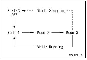
NOTE
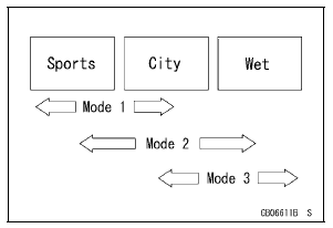
Mode 1: S-KTRC least restrictive among the three modes.
This makes lengthy drifts and wheelies possible when exiting tight corners.
Mode 2: There is more S-KTRC interaction compared to mode 1. This makes slight drifts possible when exiting tight corners.
Mode 3: S-KTRC intervenes to prevent the rear wheel from spinning whenever possible.
 System Components
 Technical Information-Power Mode
Transmission Shaft Assembly
Apply molybdenum disulfide oil solution to the sliding surfaces
of the gears and shafts.
Install the gears and the gear bushings [A] with their holes
[B] aligned.
Replace any circlips removed with new ones.
Install the circlips [A] so that the opening [B] of it is aligned
with ...
Terminal Numbers of ECU Connectors
1. Subthrottle Valve Actuator: Y/BK
2. Subthrottle Valve Actuator: BK/O
3. Unused
4. Front Wheel Rotation Sensor Signal: G/Y
5. Unused
6. Starter Lockout Switch: R/G
7. Gear Position Switch: G/R
8. Crankshaft Sensor (–): BK
9. Power Supply to Sensors: BL
10. Unused
11. Intake Air Pre ...
Exploded View
10. US, CA, CAL and AU Models
11. ZX1000JD/KD
G: Apply grease.
L: Apply a non-permanent locking agent.
R: Replacement Parts
S: Follow the specified tightening sequence.
1. US, CA and CAL Models
2. ZX1000J Model
3. ZX1000K Model
4. AU Model
5. Face the large diameter side re ...