
NOTE
Split the crankcase again, measure each clearance between the bearing insert and journal [B] using plastigage (press gauge).
Crankshaft Main Bearing Insert/Journal Clearance
Standard: 0.010  0.034 mm
(0.0004  0.0013 in.)
Service Limit: 0.06 mm (0.0024 in.)
If the clearance is within the standard, no bearing replacement is required.
If the clearance is between 0.035 mm (0.0014 in.) and the service limit (0.06 mm, 0.0024 in.), replace the bearing inserts [A] with inserts painted blue [B]. Check insert/journal clearance with the plastigage. The clearancemay exceed the standard slightly, but it must not be less than the minimum in order to avoid bearing seizure.
If the clearance exceeds the service limit, measure the diameter of the crankshaft main journal.
Crankshaft Main Journal Diameter
Standard: 34.984 35.000 mm
(1.3773  1.3780 in.)
Service Limit: 34.96 mm (1.3764 in.)
If any journal has worn past the service limit, replace the crankshaft with a new one.
If themeasured journal diameters [C] are not less than the service limit, but do not coincide with the original diameter markings [D] on the crankshaft, make new marks on it.
Crankshaft Main Journal Diameter Marks
None 34.984  34.992 mm (1.3773
 1.3776 in.)
1 34.993  35.000 mm (1.3777
 1.3780 in.)
 : Crankshaft Main Journal
Diameter Marks (“1” or No
Mark)
[A]: Crankcase Main Bearing Inside Diameter Marks, “” or no mark.
NOTE
The mark already on the upper crankcase half should almost coincide with the measurement.
Crankcase Main Bearing Inside Diameter Marks
38.000 38.008 mm (1.4961
1.4964 in.)
None 38.009 38.016 mm (1.4964
1.4967 in.)
Size Color [B]
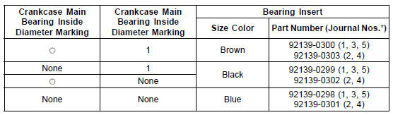
*: The bearing inserts for Nos. 2 and 4 journals have an oil groove, respectively.
 Crankshaft Runout Inspection
 Pistons
Handlebar Installation
Apply a non-permanent locking agent to the threads of
the handlebar positioning bolts and tighten them.
Torque - Handlebar Positioning Bolts: 9.8 N·m (1.0 kgf·m,
87 in·lb)
Install the steering stem head with handlebars.
Install the washer [A] and steering stem head nut [B].
Tighten:
...
Tie-Rod Removal
Squeeze the brake lever slowly and hold it with a band
[A].
Remove the front footpeg bracket bolts [A].
Raise the rear wheel off the ground with the jack (see
Rear Shock Absorber Removal).
Special Tools - Jack: 57001-1238
Jack Attachment: 57001-1608
Remove:
Upper ...
Starter Motor Disassembly
Remove the starter motor (see Starter Motor Removal).
Take off the starter motor through bolts [A] and remove
the both end covers [B].
Pull out the armature [A] out of the yoke [B].
NOTE
Do not remove the circlip [C] from the shaft.
Remove the starter motor terminal lock ...