
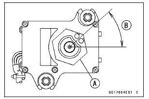
41.7° ±7° [B]
This position is original position of the pulley.
NOTE
Correct the position electrically after confirming the use is discontinued and there is no damage when differing from the angle of shown in the figure.
NOTICE
Do not correct the pulley position with the tool, forcibly. The actuator damage will occur.
If the angle is wrong, adjust the pulley (see Exhaust Butterfly Valve Actuator Installation in the Self-Diagnosis System chapter).
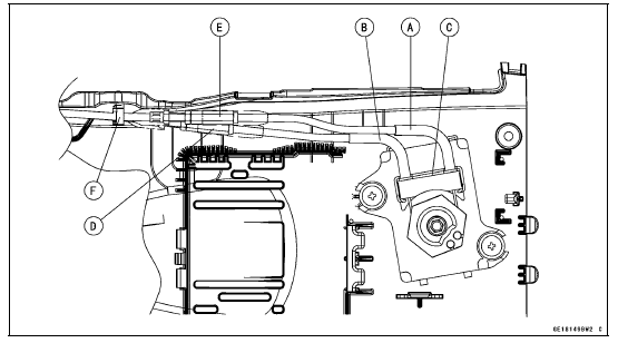
Open Cable (White) [A] Close Cable (Black) [B]
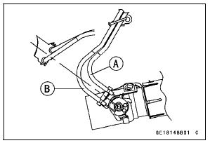
First, install the close cable (black) [A].
Second, install the open cable (white) [B].
Third, install the clamp [C].
Fourth, stretch the open cable (white) by using the adjuster [D].
Turn the adjuster counterclockwise until the play of the open cable becomes no play.
NOTICE
To keep the correct exhaust butterfly valve position, be sure to adjust the open cable first. Do not overstretch the cable.
Fifth, tighten the adjuster locknut (white) of the open cable securely.
Sixth, stretch the close cable (black) by using the adjuster [E].
Turn the adjuster counterclockwise until the play of the close cable becomes no play.
Seventh, turn the adjuster of the close cable (black) clockwise by 1/2 to 1 rotation.
Lastly, tighten the adjuster locknut (black) of the close cable securely.
 Exhaust Butterfly Valve Cable Removal
 Clutch
Warning/Indicator Lights
: When the
transmission is in
neutral, the neutral indicator light goes
on.
: When the
headlight is on high
beam, the high beam indicator light
goes on.
: When the
turn signal switch is
pushed to the left or right, the turn signal
indicator light blinks. ...
ESD (Electronic Steering Damper) ECU Communication Error (Service Code 3C,
ZX1000JD/KD)
ESD ECU Communication Line Inspection
When the data (for status of ESD system) is not sent from
the ESD ECU to the meter unit and ECU, the service code
3C is displayed.
The data is sent through the CAN communication line.
The service code 3C is detected with the meter unit.
The FI symbol does ...
Rebound Damping Force Adjustment
The rebound damping force adjuster
is located at the upper end of the rear
shock absorber.
A. Rebound Damping Force Adjuster
B. To increase damping force
C. To decrease damping force
Using a screwdriver turn the rebound
damping force adjuster clockwise
to increase rebound damping or ...