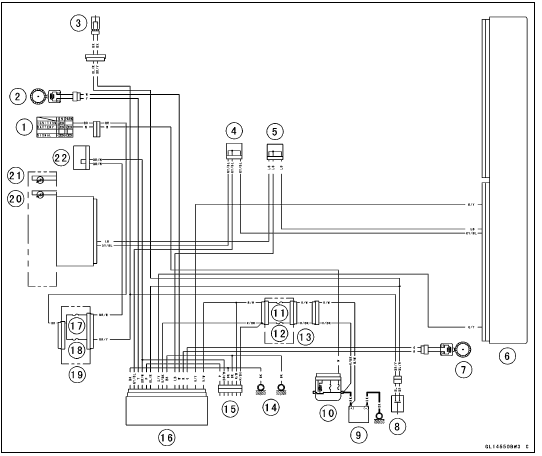


1. Ignition Switch
2. Front Wheel Rotation Sensor
3. Front Brake Light Switch
4. Joint Connector C
5. Joint Connector D
6. ECU
7. Rear Wheel Rotation Sensor
8. Rear Brake Light Switch
9. Battery 12 V 8.6 Ah
10. Main Fuse 30 A
11. KIBS Motor Relay Fuse 30 A
12. KIBS Solenoid Valve Relay Fuse 20 A
13. Fuse Box 3
14. Frame Grounds
15. KIBS Kawasaki Self-diagnosis System Connector
16. KIBS Hydraulic Unit
17. Ignition Fuse 15 A
18. Brake Light/Horn Fuse 10 A
19. Fuse Box 1
20. KIBS Indicator Light (LED) with KIBS Symbol
21. ABS Indicator Light (LED)
22. Joint Connector F
Color Codes:
BK: Black
BL: Blue
BR: Brown
CH: Chocolate
DG: Dark Green
G: Green
GY: Gray
LB: Light Blue
LG: Light Green
O: Orange
P: Pink
PU: Purple
R: Red
V: Violet
W: White
Y: Yellow
 Parts Location
 KIBS Hydraulic Unit Terminal Names
Brake Pedal Removal
Remove:
Rear Master Cylinder Mounting Bolts [A]
Foot Guard [B]
Screw and Stopper [C]
Bolt [D]
Front Footpeg Bracket Bolts [E]
Cable Guide [F]
Remove:
Cotter Pin [A]
Joint Pin [B]
Rear Brake Light Switch Spring [C]
Return Spring [D]
Remove the brake pedal mounting b ...
Brake Fluid Leak (Brake Hose and Pipe) Inspection
For KIBS equipped models, remove the fuel tank (see
Fuel Tank Removal in the Fuel System (DFI) chapter).
Apply the brake lever or pedal and inspect the brake fluid
leak from the brake hoses [A], pipes (KIBS equipped models)
[B] and fittings [C].
If the brake fluid leaked from any posit ...
Shift Fork Guide Pin/Drum Groove Wear Inspection
Measure the diameter of each shift fork guide pin [A], and
measure the width [B] of each shift drum groove.
If the guide pin on any shift fork is less than the service
limit, the fork must be replaced.
Shift Fork Guide Pin Diameter
Standard: 6.9 7.0 mm (0.272
0.276 in.)
Service Limit: ...