
First Step
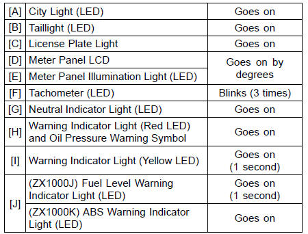
If the following light does not go on, inspect the meter unit (see Meter Unit Inspection in the Electrical System chapter).
Meter Panel LCD
Meter Panel Illumination Light (LED)
Neutral Indicator Light (LED)
Warning Indicator Light (Red LED)
Warning Indicator Light (Yellow LED)
(ZX1000J) Fuel Level Warning Indicator Light (LED)
(ZX1000K) ABS Warning Indicator Light (LED)
If the light does not go on, inspect or replace the following parts.
Battery (see Charging Condition Inspection in the Electrical System chapter) City Light (see City Light Removal/Installation in the Electrical System chapter) License Plate Light Bulb (see License Plate Light Bulb Replacement in the Electrical System chapter) ECU (see ECU Power Supply Inspection in the Fuel System (DFI) chapter) Main Fuse 30 A, Meter Fuse 10 A and Brake Light/Horn Fuse 10 A (see Fuse Inspection in the Electrical System chapter) Ignition Switch (see Switch Inspection in the Electrical System chapter) Oil Pressure Switch (see Switch Inspection in the Electrical System chapter) Gear Position Switch (see Gear Position Switch Inspection in the Electrical System chapter) Harness (see Wiring Inspection in the Electrical System chapter)
For models equipped with an immobilizer system, warning indicator light (Red LED) will blinks. Refer to the Immobilizer System (Equipped Models) section in the Electrical System chapter.
If the light does not go off, replace the ignition switch.
Second Step (∼ ZX1000JC/KC)
If the light does not go on, inspect or replace the ignition switch (see Switch Inspection in the Electrical System chapter).
Third Step
If the each light does not flash, inspect or replace the following parts.
Front Turn Signal Light (see Upper Fairing Assembly Removal/ Installation in the Frame chapter) Rear Turn Signal Light Bulb (see Rear Turn Signal Light Bulb Replacement in the Electrical System chapter) Turn Signal Indicator Light (LED) (seeMeter Unit Inspection in the Electrical System chapter) Turn Signal Relay Fuse 10 A (see Fuse Inspection in the Electrical System chapter) Turn Signal Switch (see Switch Inspection in the Electrical System chapter) Turn Signal Relay (see Turn Signal Relay Inspection in the Electrical System chapter) Harness (see Wiring Inspection in the Electrical System chapter)
If the light does not go off, inspect or replace the following parts.
Turn Signal Switch (see Switch Inspection in the Electrical System chapter) Turn Signal Relay (see Turn Signal Relay Inspection in the Electrical System chapter)
Fourth Step
If the low beam headlight does not go on, inspect or replace the following parts.
Headlight Low Beam Bulb (see Headlight Bulb Replacement in the Electrical System chapter) Headlight Fuse 15 A (see Fuse Inspection in the Electrical System chapter) Dimmer Switch (see Switch Inspection in the Electrical System chapter) Headlight Relay (see Relay Circuit Inspection in the Electrical System chapter) Harness (see Wiring Inspection in the Electrical System chapter)
If the high beam headlight and/or high beam indicator light (LED) does not go on, inspect or replace the following parts.
Headlight High Beam Bulb (see Headlight Bulb Replacement in the Electrical System chapter) Dimmer Switch (see Switch Inspection in the Electrical System chapter)
If the headlights and high beam indicator light (LED) does go off, inspect or replace the headlight relay (see Relay Circuit Inspection in the Electrical System chapter).
Headlight Aiming Inspection
If the headlight beam points to one side rather than straight ahead, adjust the headlight aiming.
 Headlight Aiming Adjustment
Fuel Consumption
This display mode shows the fuel
consumption in Liter or Gallon by numerical
value counted from the start of
measuring to present time.
A. Fuel Consumption
B. “L”
While the fuel consumption is displayed,
push the lower button and
hold it in until the fuel consumption
values re ...
Fuel Pump Relay Inspection
Refer to the Relay Circuit Inspection in the Electrical System
chapter.
If the fuel pump relay is normal, check the wiring to the
fuel pump relay (see Fuel Pump Relay Circuit).
Special Tool - Hand Tester: 57001-1394
If the wiring is good, check the ECU for its ground and
power supply (se ...
Terminal Numbers of ECU Connectors
1. Subthrottle Valve Actuator: Y/BK
2. Subthrottle Valve Actuator: BK/O
3. Unused
4. Front Wheel Rotation Sensor Signal: G/Y
5. Unused
6. Starter Lockout Switch: R/G
7. Gear Position Switch: G/R
8. Crankshaft Sensor (–): BK
9. Power Supply to Sensors: BL
10. Unused
11. Intake Air Pre ...
